Wire tensioner

Active Publication Date: 2012-11-29
SAMWOO GEOTECH
View PDF15 Cites 13 Cited by
  • Summary
  • Abstract
  • Description
  • Claims
  • Application Information

AI Technical Summary

Benefits of technology

[0010]An embodiment of the present invention is directed to a wire tensioning apparatus which is configured to allow a plurality of rods connected to a plurality of wires to be operated separately so that only a necessary rod can be operated, thereby minimizing power loss.
[0011]Another embodiment of t

Problems solved by technology

In case of the upper structure, there occurs a deflection phenomenon caused by a repetitive fatigue load and a repeated load or a self-weight load during or after the installation of the upper structure.
As a result, a problem is caused in that th

Method used


Image

  • Wire tensioner
  • Wire tensioner
  • Wire tensioner

Examples


Example

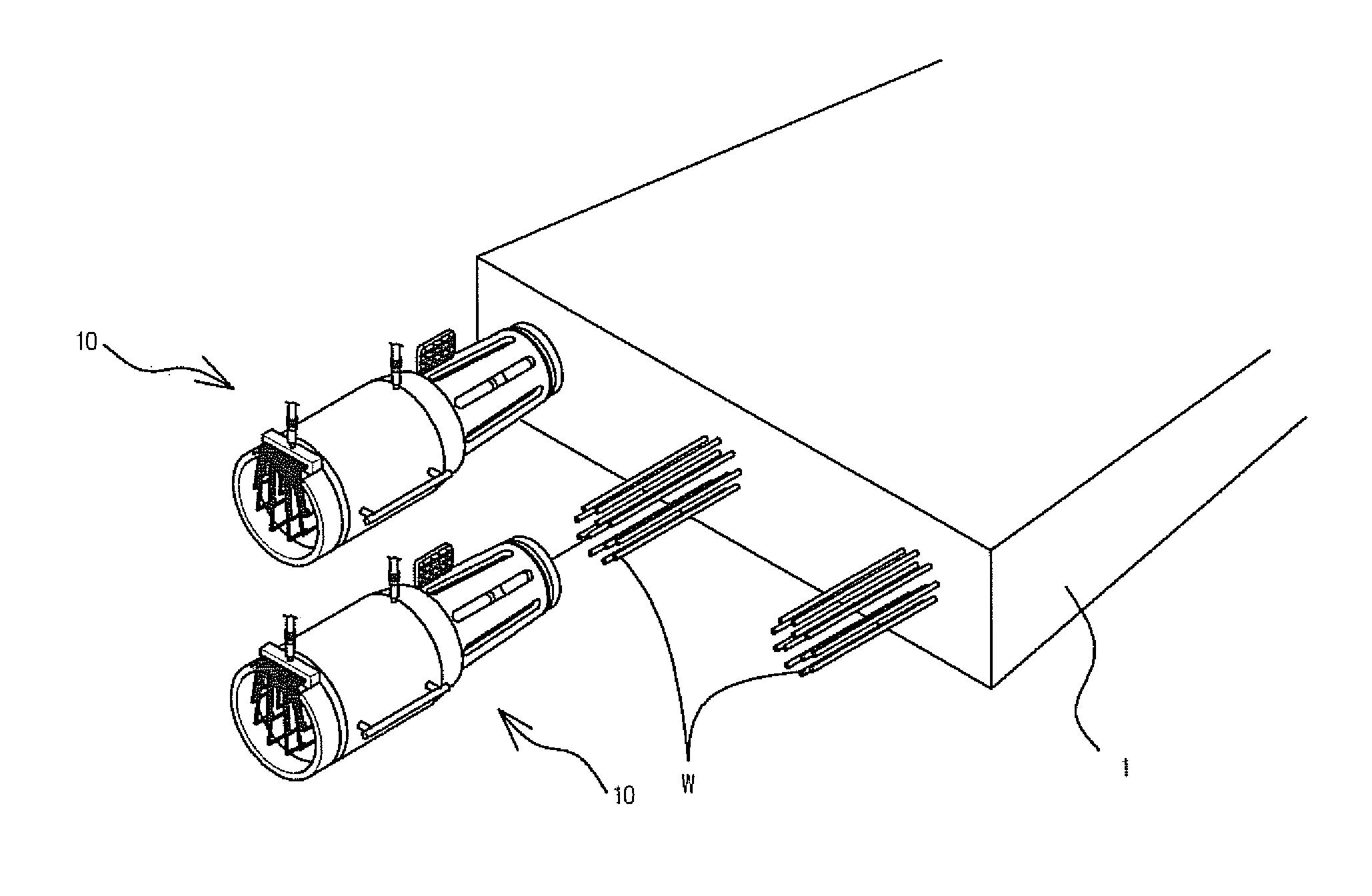
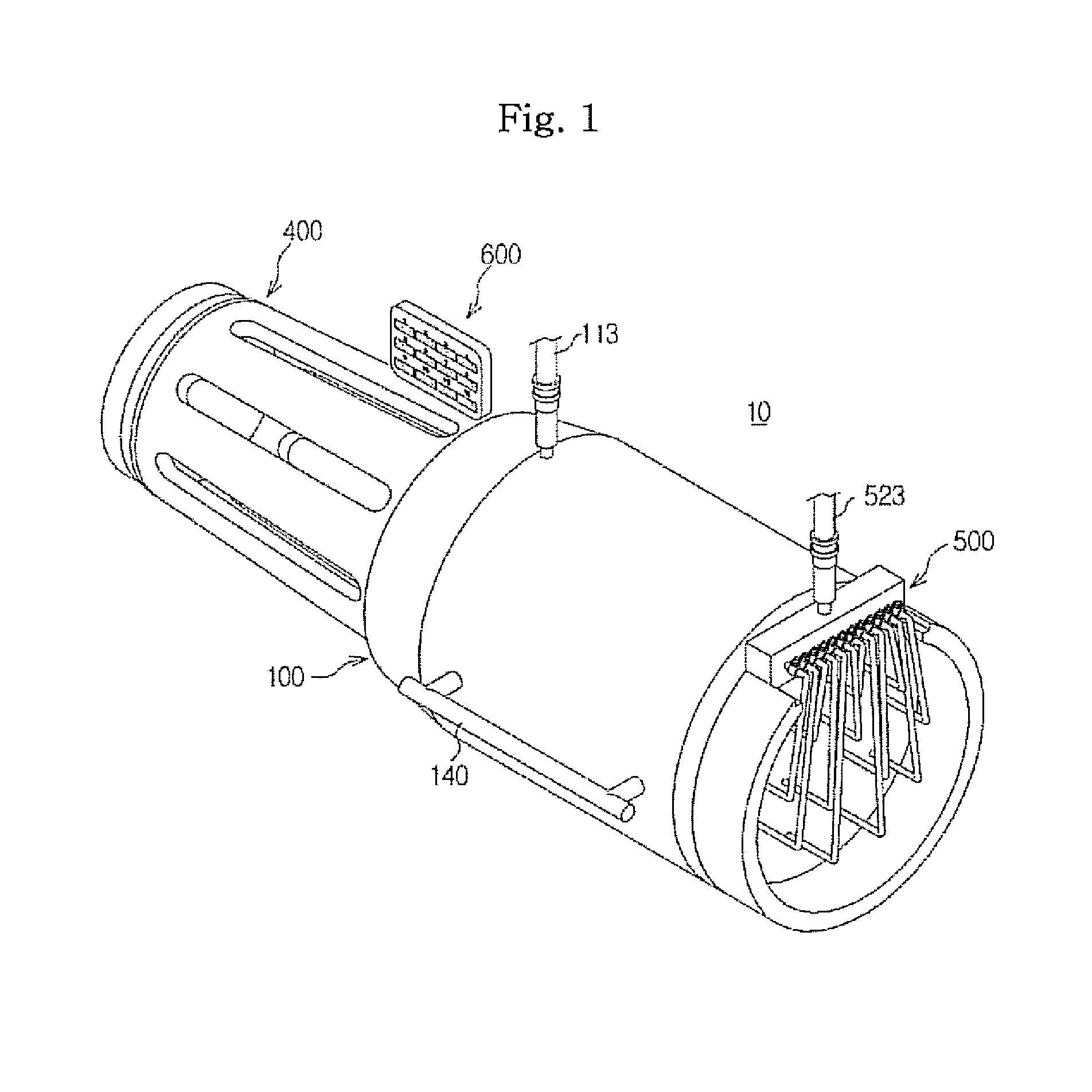
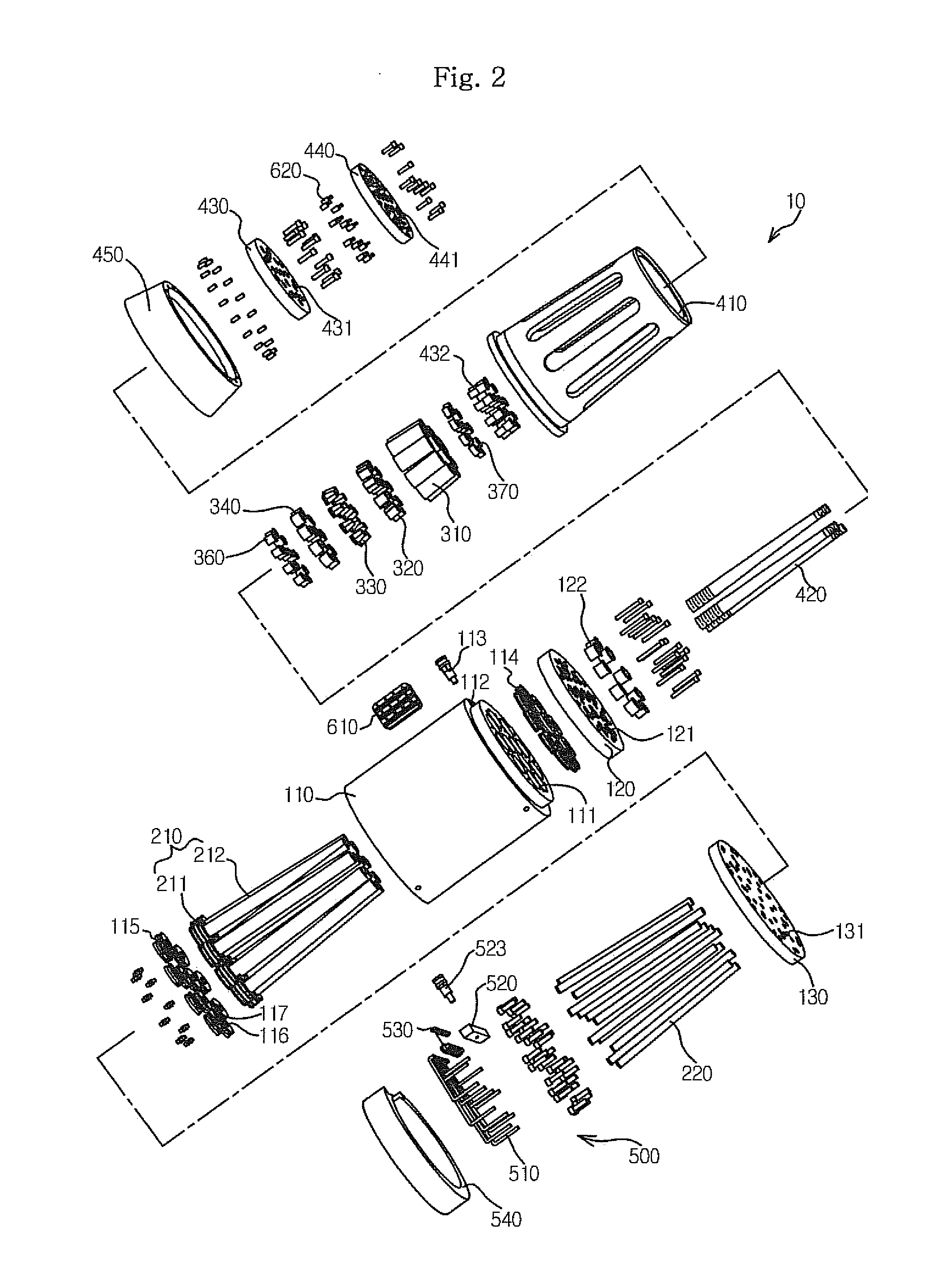
[0029]Exemplary embodiments of the present invention will be described below in more detail with reference to the accompanying drawings. The present invention may, however, be embodied in different forms and should not be construed as limited to the embodiments set forth herein. Rather, these embodiments are provided so that this disclosure will be thorough and complete, and will fully convey the scope of the present invention to those skilled in the art. Throughout the disclosure, like reference numerals refer to like parts throughout the various figures and embodiments of the present invention.

[0030]A wire tensioning apparatus according to an exemplary embodiment of the present invention will be described hereinafter with reference to FIGS. 1 to 4.

[0031]FIG. 1 is a perspective view illustrating a wire tensioning apparatus according to the present invention; FIG. 2 is an exploded perspective view illustrating the wire tensioning apparatus shown in FIG. 1; FIG. 3 is an exploded cros...


PUM


Abstract

A wire tensioner includes one or more rods configured to separately support one or more wires withdrawn from a structure and introduce a tensile force to be imparted to the wires; a fluid pressure provider configured to provide fluid pressure to the plurality of rods in order to allow the rods to exhibit the tensile force, and a fluid controller connected at one side thereof to each of the rods and connected at the other side thereof to the fluid pressure provider, and configured to selectively interrupt fluid pressure provided to the plurality of rods to control the operation of the respective rods separately.

Description

CROSS-REFERENCE TO RELATED APPLICATIONS[0001]This application is a continuation of PCT / KR2009 / 005199 filed on Sep. 11, 2009, which claims priority of Korean patent application number 10-2009-0036930 filed on Apr. 28, 2009. The disclosure of each of the foregoing applications is incorporated herein by reference in its entirety.BACKGROUND OF THE INVENTION[0002]The present invention relates to a wire tensioning apparatus for pulling wires arranged inside a structure to reinforce the structure.[0003]In general, an elevated structure that is built to span a river, a strait, a canal, a traffic route, or a structure to provide passage over it is referred to as a bridge.[0004]Such a bridge consists of an upper structure that allows for passage, and a lower structure that supports the upper structure. In case of the upper structure, there occurs a deflection phenomenon caused by a repetitive fatigue load and a repeated load or a self-weight load during or after the installation of the upper ...

Claims


Application Information

Patent Timeline
IPC IPC(8): E04C5/12E04B1/38G05B13/00
CPCE04G21/12E04C5/122E01D22/00E01D2/00
Inventor KIM, JEONG-RYEOLOH, WOON-SEOK
Owner SAMWOO GEOTECH
Why Eureka
Try Eureka