Radial shaft seal, and method for sealing a rotating machine part by means of a radial shaft seal

A technology of sealing system and mechanical parts, applied in the direction of engine components, mechanical equipment, engine sealing, etc., can solve the problems of power loss increase and emission, and achieve the effect of small power loss and long service life

Inactive Publication Date: 2018-10-23
KACO
View PDF6 Cites 0 Cited by
  • Summary
  • Abstract
  • Description
  • Claims
  • Application Information

AI Technical Summary

Problems solved by technology

This power loss increases the vehicle's CO 2 emission

Method used


Image

  • Radial shaft seal, and method for sealing a rotating machine part by means of a radial shaft seal
  • Radial shaft seal, and method for sealing a rotating machine part by means of a radial shaft seal
  • Radial shaft seal, and method for sealing a rotating machine part by means of a radial shaft seal

Examples


Embodiment Construction

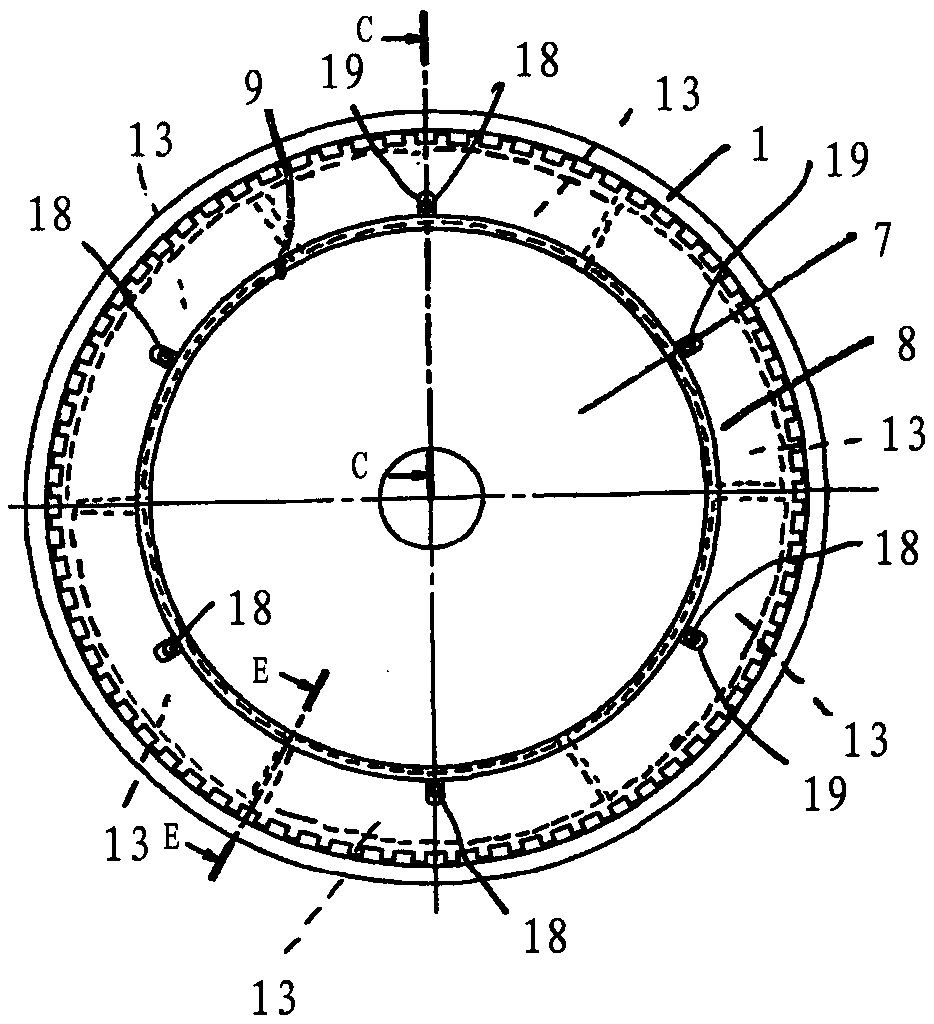
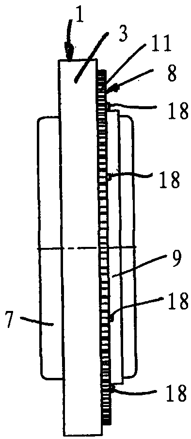
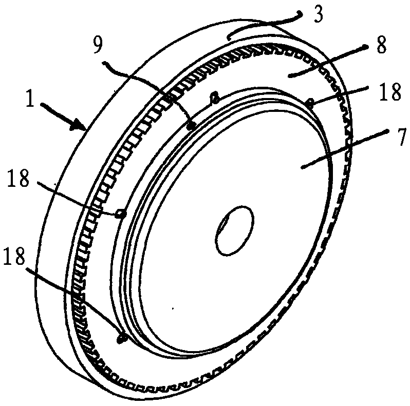
[0038] The feature of the radial shaft sealing system described below is that the sealing lip of the radial shaft sealing system rests against the radial shaft sealing system and seals with full radial force in the static state of the shaft to be sealed. As long as the shaft is rotatably driven, the sealing lip is lifted from the rotating shaft or rests on the shaft with only a small radial force. In this way, the power loss caused by friction loss is minimized. This also results in that the sealing lip only experiences small wear and the radial shaft sealing system has a long life.

[0039] The radial shaft sealing system has an annular housing 1 having an L-shaped cross section ( Figure 5 ). The housing has a cylindrical peripheral surface 2 to which a flange 3 directed radially inward is connected. A ring-shaped fixing member 5 is used to fix the sealing ring 4 on the inner side of the flange. The sealing ring 4 is advantageously a PTFE ring, which is fixed to the radial f...


PUM


Abstract

The invention relates to a radial shaft seal having a sealing element, which has a sealing lip (6), which, in a sealing position, lies on a rotatably driven machine part (7) to be sealed. In order tokeep the friction losses low, the sealing lip (6) is surrounded by at least two centrifugal force elements (13), which are held on at least one carrier (8) connected to the machine part (7) for conjoint rotation and which load the sealing lip (6) radially in the sealing position when the machine part (7) is at rest and relieve the sealing lip when the machine part (7) is rotating. In the method for sealing a rotating machine part (7) by means of a radial shaft seal, the sealing lip (6) is pressed against the machine part (7) by the centrifugal force elements (13) when the machine part (7) is at rest and, at an idling rotational speed of the machine part (7) at the latest, the centrifugal force elements (13) are moved outward so far that the sealing lip (6) lies against the rotating machinepart (7) with at least reduced force.

Description

Technical field [0001] The invention relates to a radial shaft sealing system according to the preamble of claim 1 and a method for sealing rotating mechanical parts according to the preamble of claim 15. Background technique [0002] In the known radial shaft sealing system, the sealing lip always rests on the rotating mechanical part and thus ensures sealing. Due to the friction between the sealing lip and the rotating mechanical parts, high friction losses occur. The high friction loss also causes corresponding wear of the sealing element. [0003] In particular, when the rotating mechanical component is an internal combustion engine crankshaft, high friction loss occurs due to the long-term contact between the sealing lip and the shaft under high radial force. This power loss increases the CO of motor vehicles 2 emission. Summary of the invention [0004] The object of the present invention is to construct the radial shaft sealing system of the type and the method of the type...

Claims


Application Information

Patent Timeline
Patent Type & Authority Applications(China)
IPC IPC(8): F16J15/16F16J15/3212F16J15/322F16J15/3228
CPCF16J15/164F16J15/3212F16J15/322F16J15/3228
Inventor M·帕尔默
Owner KACO
Why Eureka
Try Eureka