Switching power source device

Inactive Publication Date: 2007-03-29
SANKEN ELECTRIC CO LTD
View PDF3 Cites 1 Cited by
  • Summary
  • Abstract
  • Description
  • Claims
  • Application Information

AI Technical Summary

Benefits of technology

[0008] According to the present invention, a secondary switching element can be turned on and off in response to the periods for accumulating and discharging energy in reactor connected to a secondary winding of a transformer to perform the efficient synchronous rectification operation of sec

Problems solved by technology

However, the converter has a drawback of lowered efficiency in power conversion because a rectifying diode connected to seco

Method used


Image

  • Switching power source device
  • Switching power source device
  • Switching power source device

Examples


Example

First Embodiment

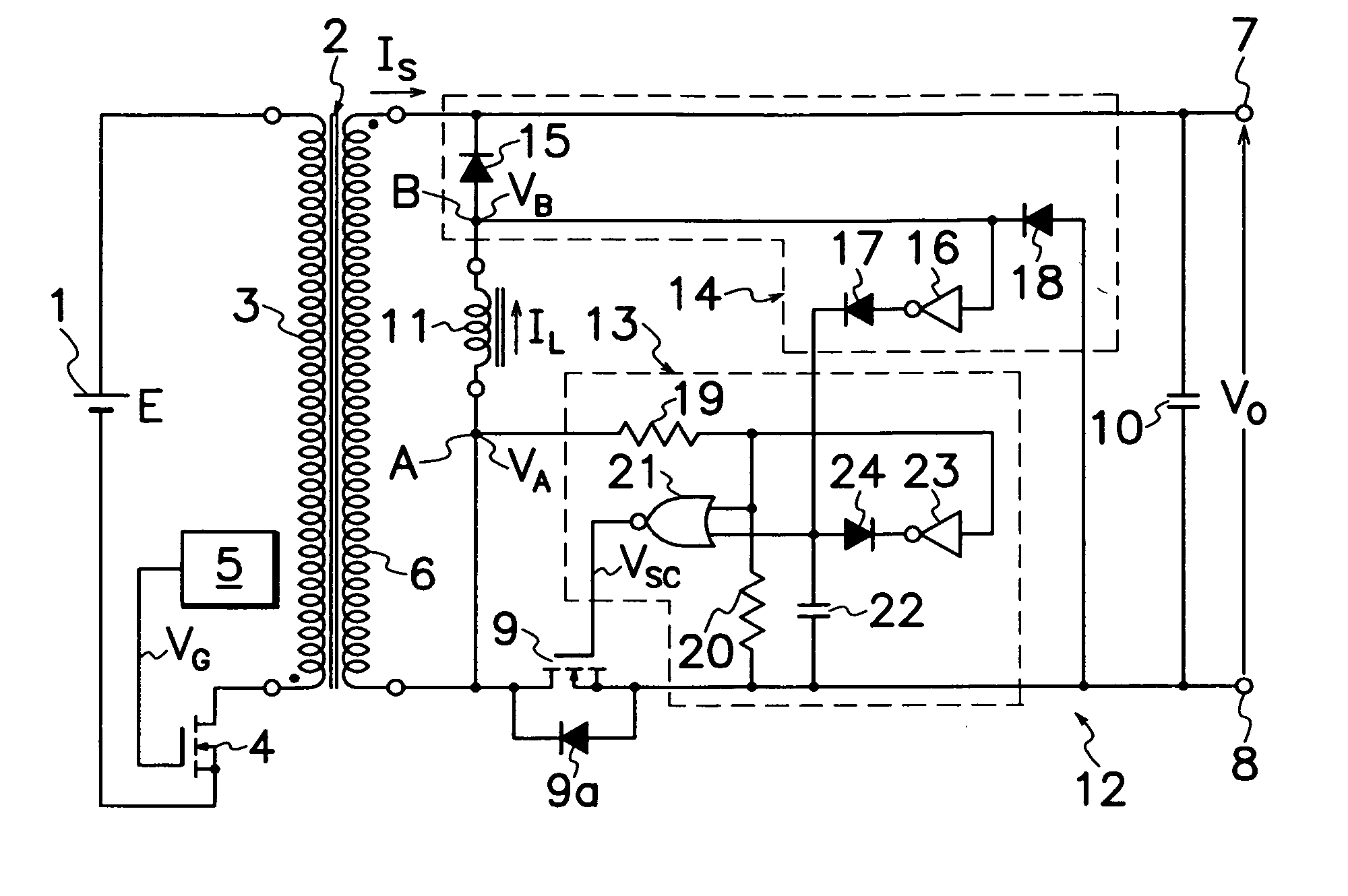
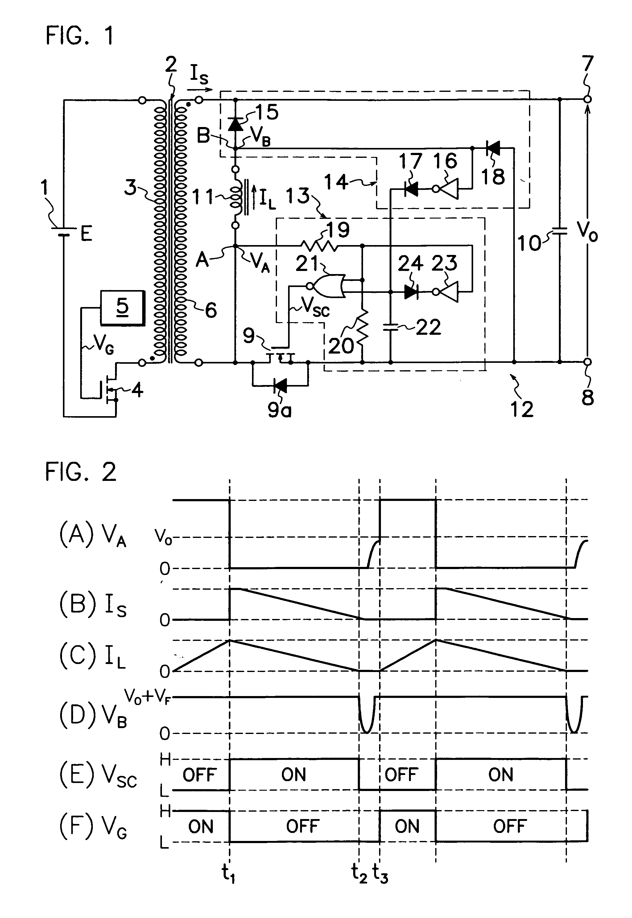
[0023]FIG. 1 illustrates a first embodiment of the switching power source device according to the present invention. The device comprises a primary winding 3 of a transformer 2 and a primary MOS-FET 4 as a primary switching element connected in series to a DC power source 1; a primary control circuit 5 for controlling to turn primary MOS-FET 4 on and off; a secondary MOS-FET 9 as a secondary switching element for synchronous rectification and an output smoothing capacitor 10 connected between a secondary winding 6 of transformer 2 and output terminals 7, 8; a reactor or choke coil 11 connected in parallel to secondary winding 6 of transformer 2 for accumulating energy during the on-period of primary switching element 4, and a secondary control circuit 12 for synchronous rectification connected to reactor 11 and a control terminal of secondary MOS-FET 9. Secondary control circuit 12 serves to retain secondary MOS-FET 9 off during the period for accumulating energy in...

Example

Second Embodiment

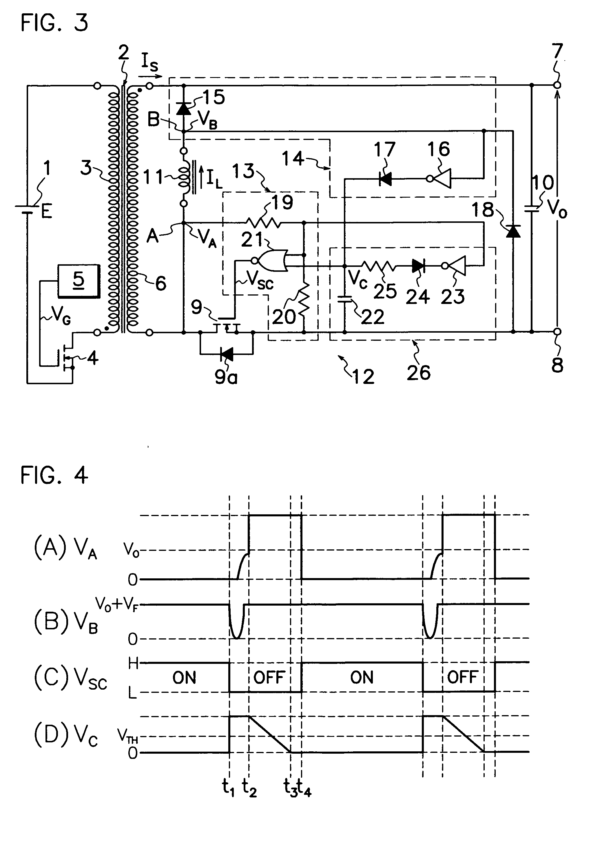
[0035] The first embodiment can be modified. By way of example, FIG. 3 illustrates a variation of the first embodiment as a second embodiment which comprises a resistor 25 connected between a junction of capacitor 22 and second diode 17 and fourth diode 24; and a retaining circuit 26 composed of capacitor 22, second inverter 23, fourth diode 24 and resistor 25. Retaining circuit 26 maintains second input terminal of NOR gate 21 at high voltage level to hold switch circuit 13 in inactive mode when voltage VA of narrow pulse width is applied on junction A of reactor 11 and dividing resistor 19. Other components are substantially similar to those in switching power source device of first embodiment shown in FIG. 1.

[0036] When a rated load not shown is connected to output terminals 7 and 8 in second embodiment shown in FIG. 3, energy release in reactor 11 is completed during the off-period of primary MOS-FET 4, and reset voltage VB on junction B falls from (VO+VF [V])...

Example

Third Embodiment

[0040]FIG. 6 shows a third embodiment of the switching power source device according to the present invention which comprises a secondary switching element or MOS-FET 9 of synchronous rectification connected between top end (marked black dot) of secondary winding 6 of transformer 2 and a positive output terminal 7; a tertiary winding 30 connected in series to secondary winding 6 of transformer 2; a first NPN transistor 31 as a reactor current detector; and a secondary control circuit 12 of synchronous rectification for controlling secondary MOS-FET 9. First NPN transistor 31 has a base terminal connected to one end of reactor 11; an emitter terminal connected to a junction of secondary and tertiary windings 6 and 30 of transformer 2; and a collector terminal connected to secondary control circuit 12 so that base terminal of first NPN transistor 31 detects electric current IL through reactor 11 to accumulate or discharge energy in reactor 11. Secondary control circui...


PUM


Abstract

A switching power source device is provided which comprises a secondary MOS-FET 9 connected between a secondary winding 6 of a transformer 2, a reactor 11 connected in parallel to secondary winding 6 of transformer 2 for accumulating energy during the on-period of primary MOS-FET 4, and a secondary control circuit 12 connected to reactor 11 and a control terminal of secondary MOS-FET 9. Secondary control circuit 12 serves to turn secondary MOS-FET 9 off to accumulate energy in reactor 11, turn secondary MOS-FET 9 on to discharge energy accumulated in reactor 11, and turn secondary MOS-FET 9 off upon completion of energy release from reactor 11. As secondary control circuit 12 turns secondary MOS-FET 9 on and off in response to the periods for accumulating and discharging energy in reactor 11, the device can perform the efficient synchronous rectification operation of secondary MOS-FET 9 even under the fluctuating condition of input and output voltages E, VO and control of power loss in output voltage VO produced from secondary winding 6 of transformer 2.

Description

TECHNICAL FIELD [0001] This invention relates to a switching power source device, in particular, of the type capable of controlling power loss for output voltage generated from a secondary winding of a transformer. BACKGROUND OF THE INVENTION [0002] A known switching power source device comprises a primary winding of a transformer and a switching element connected in series to a DC power source wherein switching element is turned on and off to cause electric current to flow through primary winding and switching element in order to generate DC power from output terminals connected to a secondary winding of transformer. When switching element is turned on, electric current passes through primary winding of transformer to accumulate electromagnetic energy in transformer, and when switching element is turned off, stored electromagnetic energy can be taken out from secondary winding in a switching power source device named “Flyback Converter”. However, the converter has a drawback of low...

Claims


Application Information

Patent Timeline
IPC IPC(8): H02M3/335H02M7/00
CPCY02B70/1475H02M3/33592Y02B70/10
Inventor KYONO, YOICHI
Owner SANKEN ELECTRIC CO LTD
Why Eureka
Try Eureka