Fracturing Nozzle Assembly with Cyclic Stress Capability
- Summary
- Abstract
- Description
- Claims
- Application Information
AI Technical Summary
Benefits of technology
Problems solved by technology
Method used
Image

Examples
Embodiment Construction
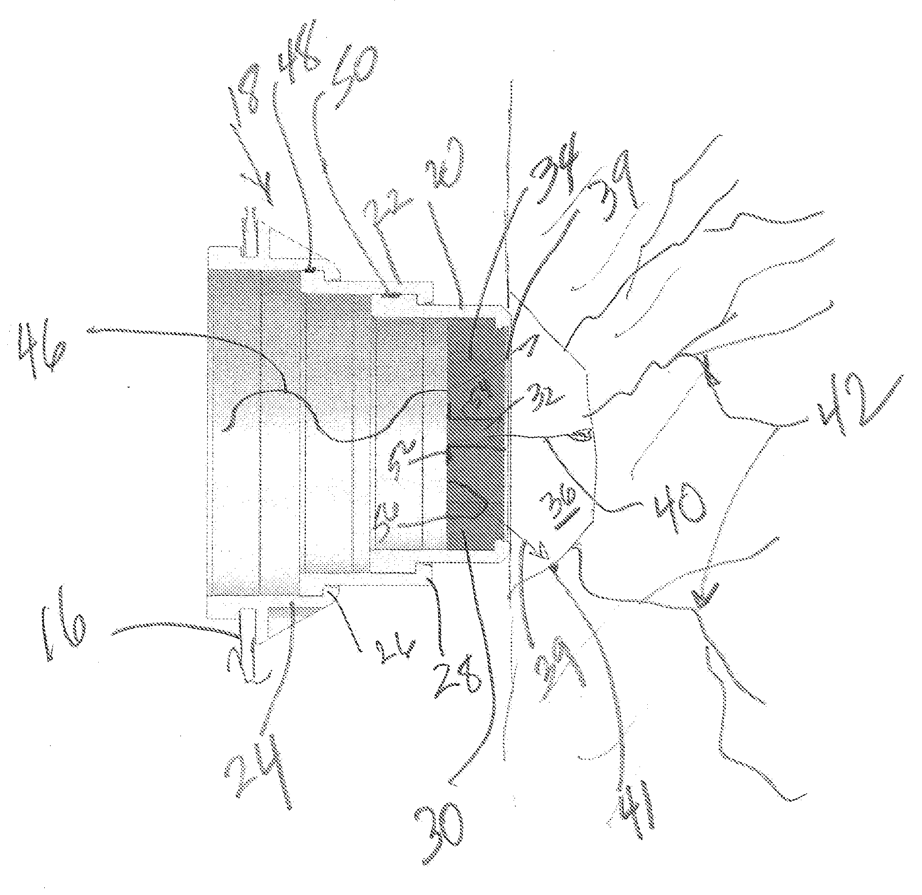
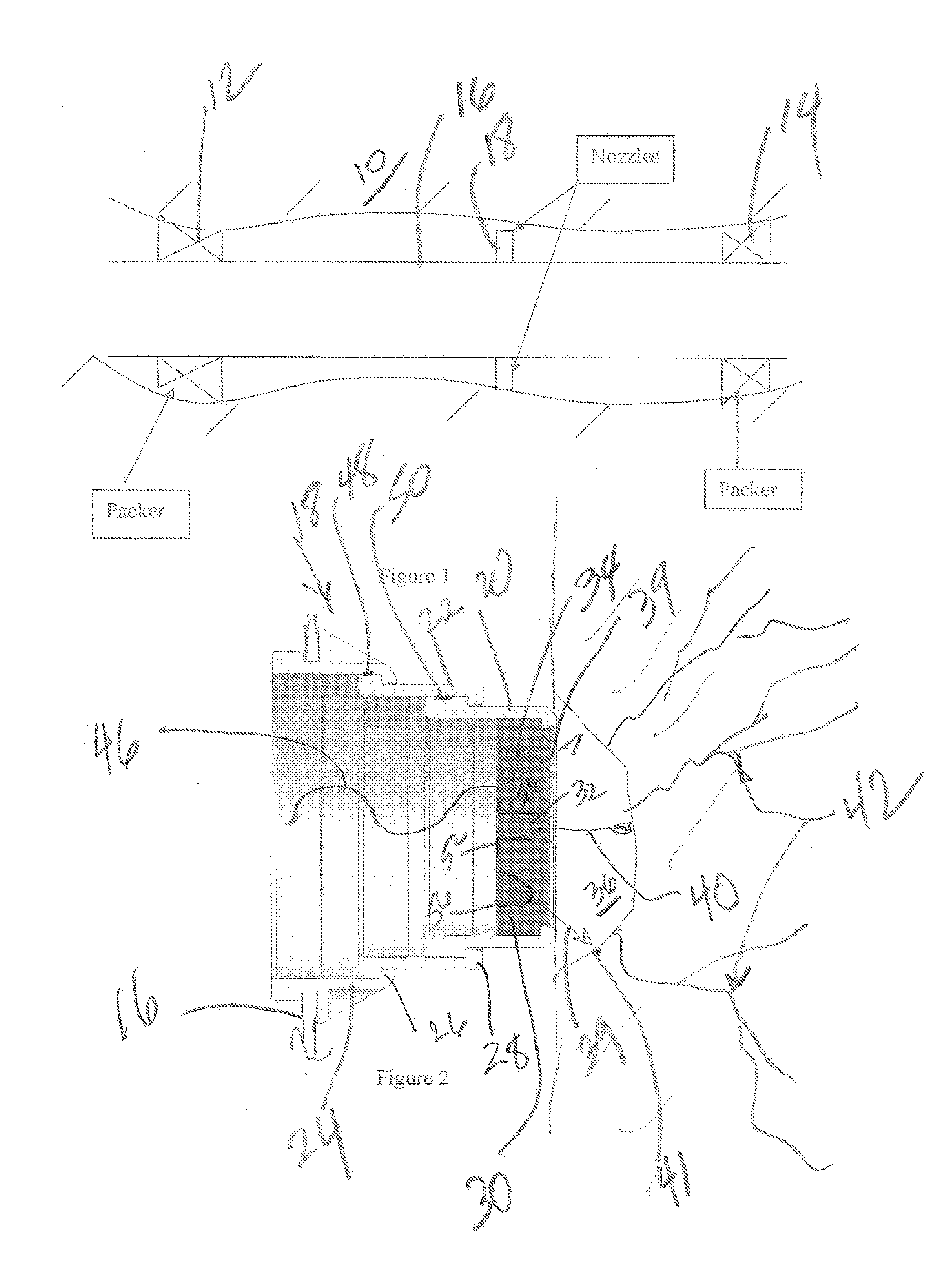
[0016]FIG. 1 shows a zone 10 isolated by packers 12 and 14 and a string 16 spanning the packers 12 and 14 and extending to the surface where the source of pressurized fluid (not shown) is located on a rig at the well site. The assembly 18 which will be described in its various embodiments below is shown schematically as an array that extends circumferentially around the string 16 and can be in a single or multiple parallel rows or can be offset spirals at for example 90 degree spacing or the pattern can be random to secure good coverage of the jet streams in the zone 10. It is understood that there can be other zones and those skilled in the art will further know that the packer 12 can be set after the zone 10 is fractured to allow fracturing to go on at a higher zone that is not shown. In that case the packer 12 is set after zone 10 is fractured to allow isolation of zone 10 when another zone is being fractured.
[0017]The assembly 18 is shown in FIG. 2 as a series of movable compone...
PUM
 Abstract
Description
Claims
Application Information