Multilayer annular clamp

Active Publication Date: 2012-11-29
KRAUSZ INDS DEVMENT
View PDF5 Cites 18 Cited by
  • Summary
  • Abstract
  • Description
  • Claims
  • Application Information

AI Technical Summary

Benefits of technology

[0005]The present invention seeks to provide an improved clamp that improves the ability of the seal to withstand such axial forces, as is described more in detail hereinbel

Problems solved by technology

However, in some applications, the seals are subjected to considerable axial forces du

Method used


Image

  • Multilayer annular clamp
  • Multilayer annular clamp
  • Multilayer annular clamp

Examples


Embodiment Construction

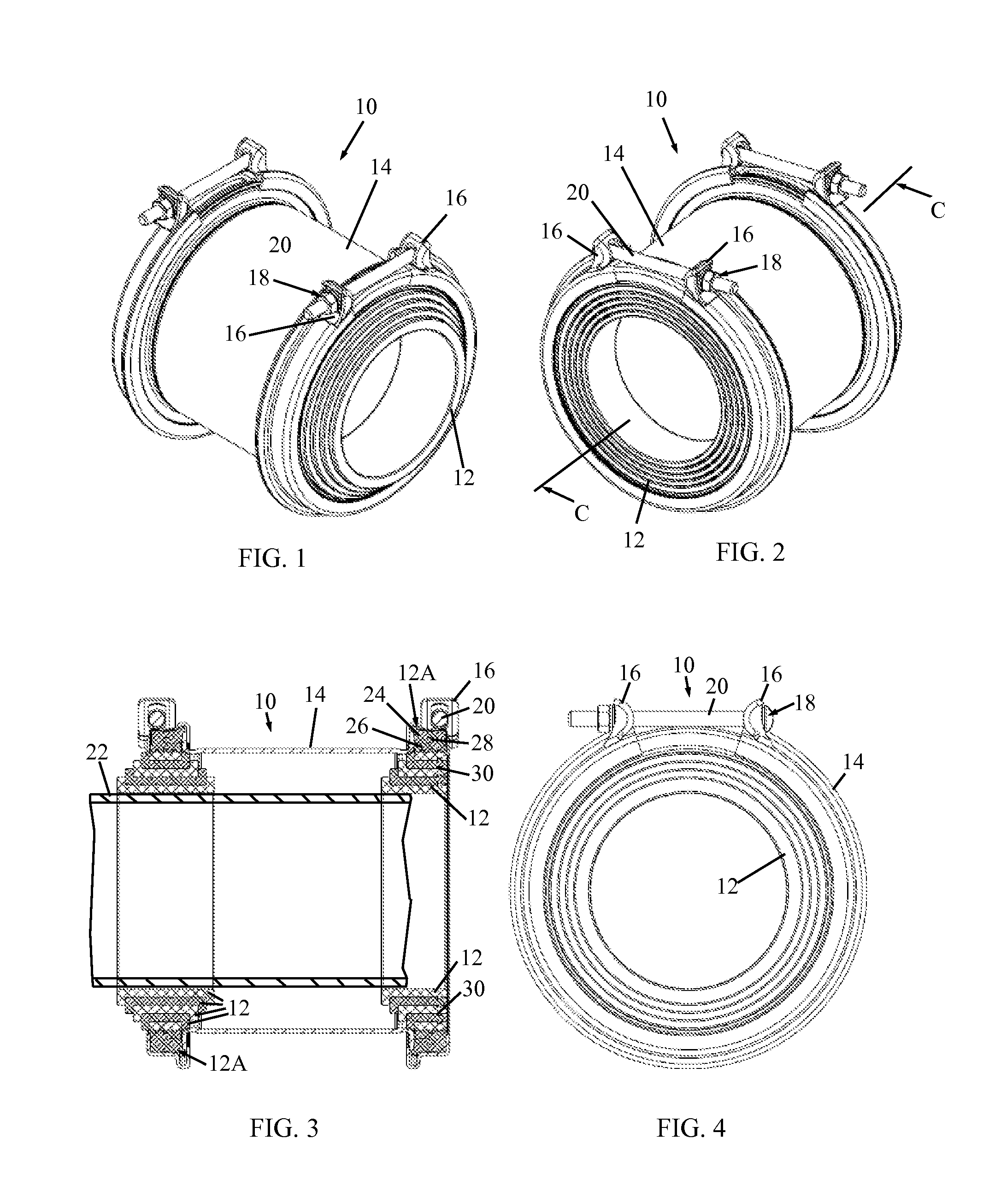
[0013]Reference is now made to FIGS. 1-4, which illustrate a multilayer annular clamp 10, constructed and operative in accordance with a non-limiting embodiment of the present invention.

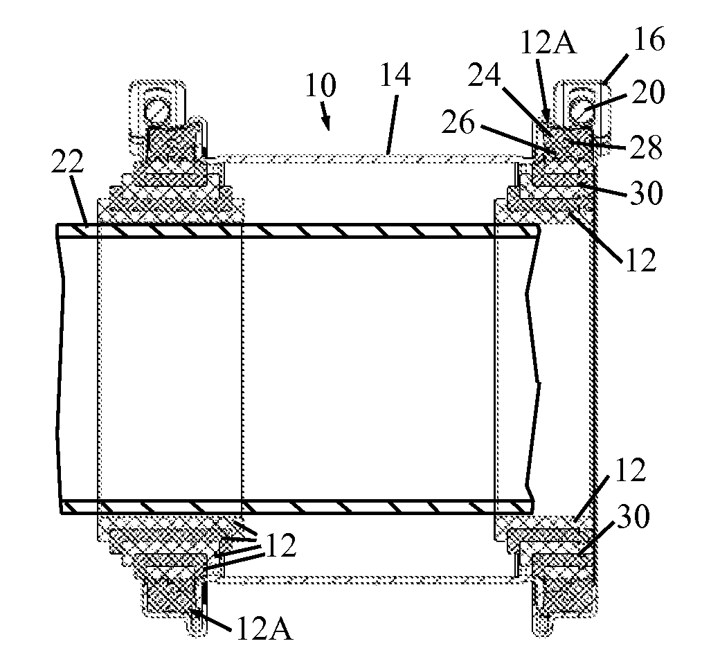
[0014]Clamp 10 includes a plurality of sealing rings 12 radially spaced from one another and disposed in a housing 14, which may be cylindrical. Two clamp members 16 are disposed around a portion of the sealing rings 12. A fastener 18, including a shank 20, such as a bolt and nut fastener, fastens the clamp members 16 towards each other in a direction along shank 20 so as to apply a radially-inward clamping force on the innermost sealing ring 12 that is arranged to contact (surround) a pipe 22 (shown partially in broken lines in FIG. 3) placed in clamp 10.

[0015]As seen in FIG. 3, the sealing rings 12 have L-shaped axial-plane cross-sections nested in one another. The innermost sealing ring 12 contacts an outer contour of pipe 22. In the embodiment of FIGS. 1-4, the right side set of sealing rings in ...


PUM


Abstract

A multilayer annular clamp including a plurality of sealing rings radially spaced from one another, at least two of the sealing rings including L-shaped axial-plane cross-sections nested in one another, an innermost one of the sealing rings being operative to contact an outer contour of the pipe, two clamp members disposed around a portion of the sealing rings, and a fastener, including a shank, operative to fasten the clamp members towards each other in a direction along the shank so as to apply a radially-inward clamping force on the innermost sealing ring that contacts the pipe so that the multilayer annular clamp clamps the pipe.

Description

FIELD OF THE INVENTION[0001]The present invention relates generally to clamps and grip rings for pipes, and particularly to a multilayer annular clamp.BACKGROUND OF THE INVENTION[0002]Many kinds of removable band-type couplings for pipes exist in the art. It is noted that throughout the specification and claims, the term “pipe” encompasses any kind of generally cylindrical object.[0003]U.S. Pat. No. 6,293,556 to Krausz describes a coupling for connecting pipes of the same or different diameters. The coupling has a ring shaped seal made of rubber or other resilient material, constructed of a first ring seal seated over a second ring seal. The seals can be easily disconnecting from one another to allow sealing against different diameter pipes. For smaller diameter pipes, both the first and second ring seals are used; for larger diameters, only one seal is used.[0004]However, in some applications, the seals are subjected to considerable axial forces due to the fluids flowing in the pip...

Claims


Application Information

Patent Timeline
IPC IPC(8): F16L21/02
CPCF16L21/022F16L25/14F16L21/065
Inventor CHIPROOT, AVI
Owner KRAUSZ INDS DEVMENT
Why Eureka
Try Eureka