Electric motor

Inactive Publication Date: 2012-11-29
JOHNSON ELECTRIC INTERNATIONAL AG
View PDF9 Cites 24 Cited by
  • Summary
  • Abstract
  • Description
  • Claims
  • Application Information

AI Technical Summary

Benefits of technology

[0005]Hence there is a desire for an electric motor which has a

Problems solved by technology

However, the winding of the above traditional brush motor has a long winding head at each axial end of the rotor core due to the overlapping of adjacent coils, which inc

Method used


Image

  • Electric motor
  • Electric motor
  • Electric motor

Examples


Example

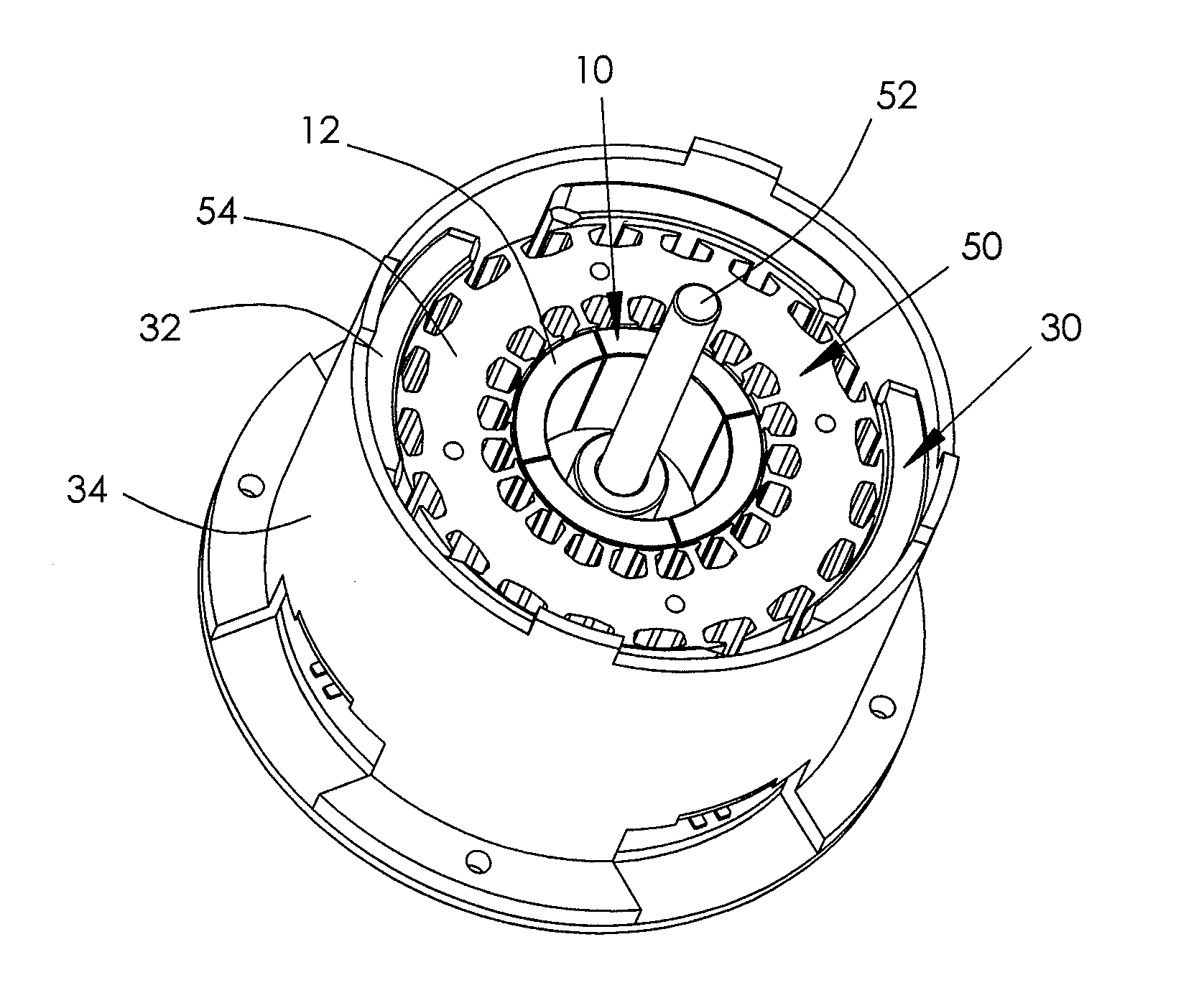
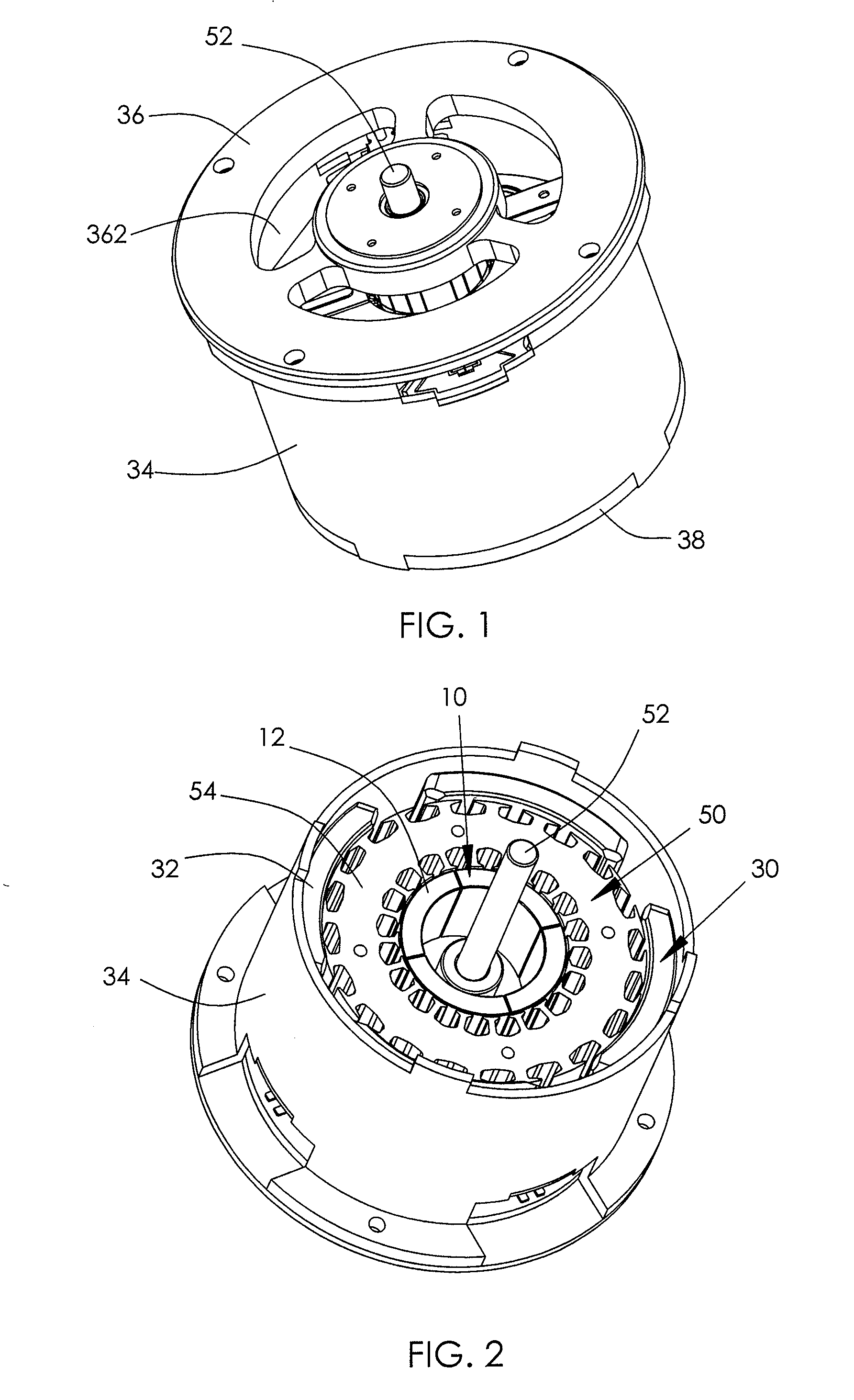
[0023]The figures illustrate an electric motor according to a preferred embodiment of the present invention. The motor comprises an inner stator 10, an outer stator 30, and a rotor 50 rotatably disposed between the inner and outer stators 10, 30.

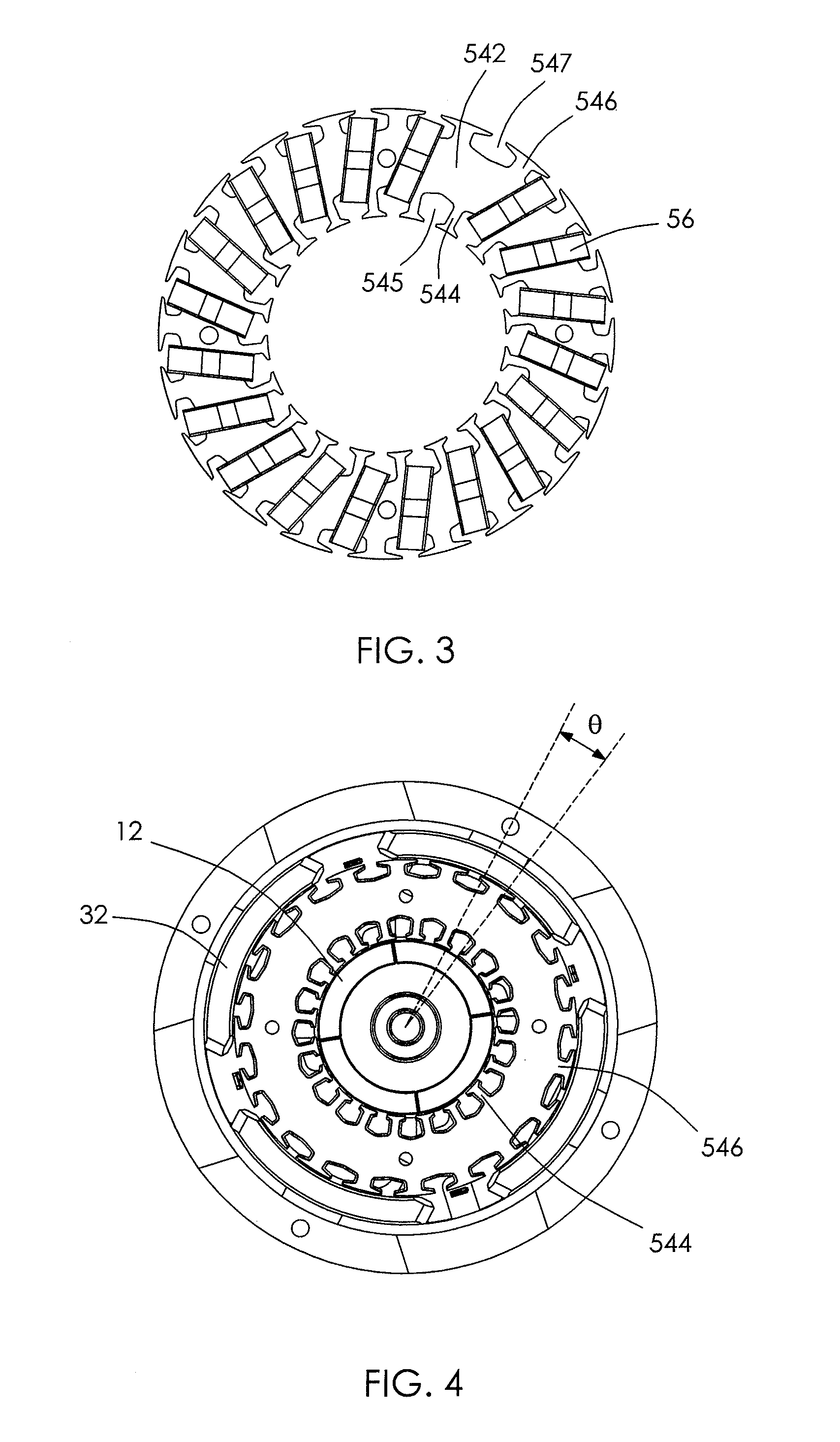
[0024]The rotor 50 comprises a shaft 52, a rotor core 54 fixed on the shaft 52, and a rotor winding 56 wound on the rotor core 54. The rotor core 54 is made of magnetic material and comprises a ring shaped yoke 542. The yoke has a plurality of inner teeth 544 extending inwardly from the yoke 542 and a plurality of outer teeth 546 extending outwardly from the yoke 542. The rotor winding 56 comprises a plurality of coils wound on the yoke 542. Each coil comprises an inner side received in a corresponding inner slot 545 formed between adjacent inner teeth 544 and an outer side received in a corresponding outer slot 547 formed between adjacent outer teeth 546. The inner slot 545 and outer slot 547 for the same coil are offset in the circumferent...


PUM


Abstract

An electric motor includes an inner stator including inner magnetic poles arranged circumferentially, an outer stator including outer magnets arranged circumferentially, and a rotor rotatably disposed between the inner and outer stators. The rotor includes a shaft, a rotor core fixed to the shaft and a winding wound on the rotor core. The rotor core includes a ring shaped yoke having a plurality of inner teeth extending inwardly and a plurality of outer teeth extending outwardly. The winding includes a plurality coils each including an inner side received in a corresponding inner slot formed between adjacent inner teeth and an outer side received in a corresponding outer slot formed between adjacent outer teeth.

Description

CROSS REFERENCE TO RELATED APPLICATIONS[0001]This non-provisional patent application claims priority under 35 U.S.C. §119(a) from Patent Application No. 201110143264.9 filed in The People's Republic of China on May 26, 2011.FIELD OF THE INVENTION[0002]This invention relates to an electric motor and in particular, to an electric motor with two stators.BACKGROUND OF THE INVENTION[0003]A traditional brush motor usually comprises a stator and a rotor pivotably mounted with respect to the stator. The rotor comprises a rotor core with a plurality of radial extended teeth and a lap-type winding with a plurality of coils each wound around several teeth. Each coil has portions overlapping adjacent coils. The stator comprises one or more permanent magnets confronting the teeth of the rotor.[0004]However, the winding of the above traditional brush motor has a long winding head at each axial end of the rotor core due to the overlapping of adjacent coils, which increases the axial length of the ...

Claims


Application Information

Patent Timeline
IPC IPC(8): H02K1/26H02K9/06
CPCH02K23/04H02K23/30H02K2213/03H02K1/146H02K16/04H02K23/40
Inventor LI, YUEJIANG, MAO XIONGZHAO, JIANWANG, ZHI JUNZHANG, YA MINGXIANG, HAI HUI
Owner JOHNSON ELECTRIC INTERNATIONAL AG
Why Eureka
Try Eureka