Compact drive

Active Publication Date: 2008-11-18
SEW-EURODRIVE GMBH & CO KG
View PDF26 Cites 2 Cited by
  • Summary
  • Abstract
  • Description
  • Claims
  • Application Information

AI Technical Summary

Benefits of technology

[0003]An example embodiment of the present invention may provide a compact drive that may eliminate the above-mentioned disadvantages. For example, axial length may be reduced and as many power take-off variants as possible may be implementable, i.e., one-sided and two-sided power take-off.
[0009]The transmission region, the region of the motor, and the electronics compartment may be at approximately the same temperature. It may be provided that no thermal barriers are necessary, and therefore, material may be dispensed with and mass and costs may be reduced.
[0011]The motor may not include a sensor, but the position may be ascertained with the aid of an estimation method. This may allow axial space to be saved.

Problems solved by technology

In this context, it may be disadvantageous that the axial length is long and that a power take-off can only be provided at one end face of the compact drive.

Method used


Image

  • Compact drive
  • Compact drive
  • Compact drive

Examples


Embodiment Construction

[0077]An oblique view of a compact drive according to an example embodiment of the present invention is illustrated in FIG. 4, whereby transmission 40 is illustrated schematically.

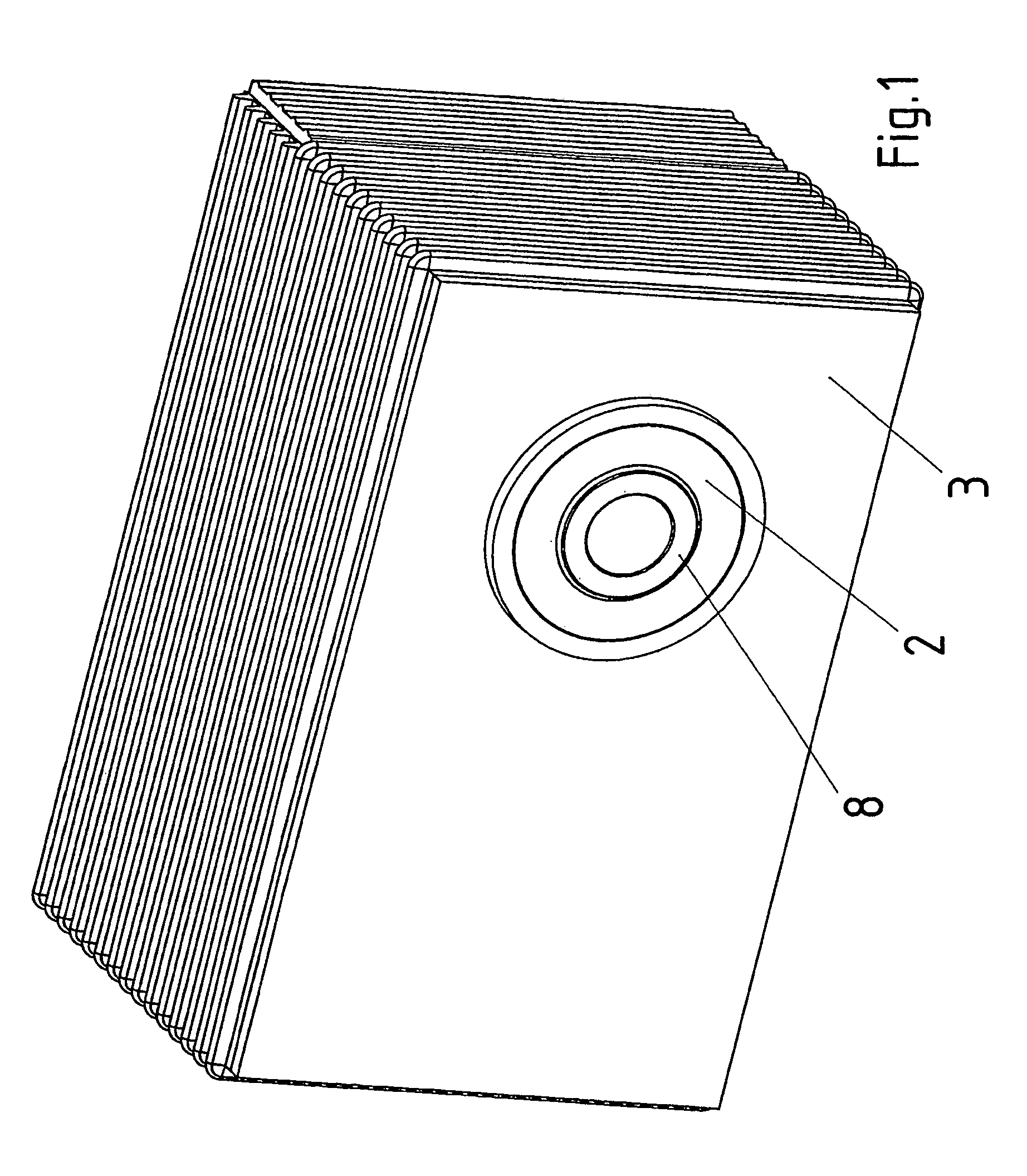
[0078]A perspective view of a compact drive according to an example embodiment of the present invention is illustrated in FIG. 1.

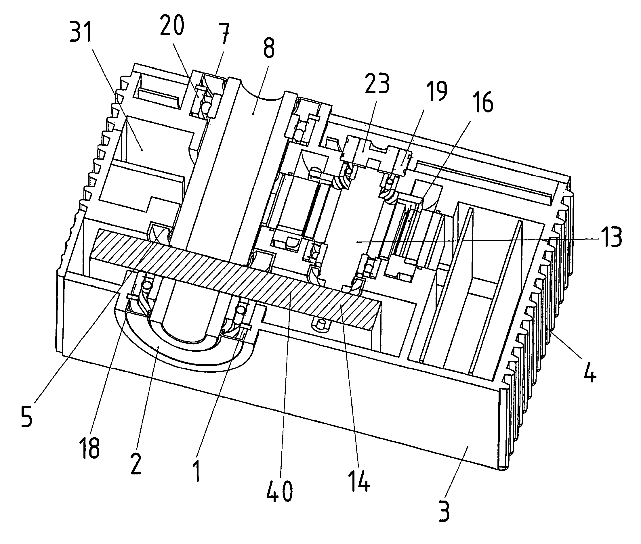
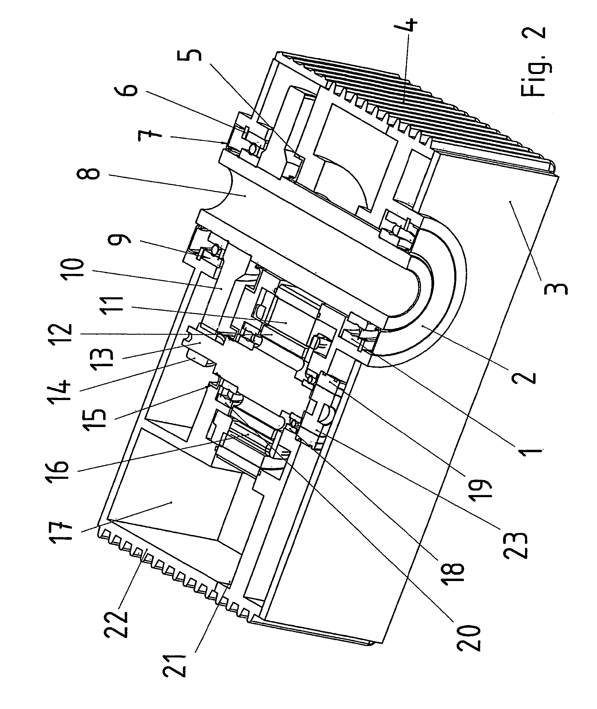
[0079]A cross-sectional view of the compact drive illustrated in FIG. 1 is illustrated in FIG. 2.

[0080]Illustrated in FIG. 3 is a cross-sectional view of a compact drive according to an example embodiment of the present invention, where, in contrast to FIG. 2, the frequency converter and the motor are arranged on different sides of the output shaft.

[0081]Illustrated in FIG. 5 is an exemplary embodiment of the present invention, in which a three-stage transmission is implemented.

[0082]FIG. 6 is a view different from that in FIG. 5.

[0083]FIG. 7 is an external view of the exemplary embodiment illustrated in FIG. 5.

[0084]In each instance, transmission 40 symbolically indicated in FIG...


PUM


Abstract

A compact drive includes at least an electric motor, a transmission, and a frequency converter, the output shaft of the transmission and the rotor shaft being parallel to each other, and the shaft-center distance at least being determined by a spur-gear stage of the transmission or by the design of a variable transmission.

Description

FIELD OF THE INVENTION[0001]The present invention relates to a compact drive.BACKGROUND INFORMATION[0002]German Published Patent Application No. 197 14 784 describes a compact drive, which includes an electric motor, at whose one end face a transmission is situated, and at whose other end face a frequency converter is situated. The electronics region and the motor region must be sealed with respect to the transmission. In this context, it may be disadvantageous that the axial length is long and that a power take-off can only be provided at one end face of the compact drive.SUMMARY[0003]An example embodiment of the present invention may provide a compact drive that may eliminate the above-mentioned disadvantages. For example, axial length may be reduced and as many power take-off variants as possible may be implementable, i.e., one-sided and two-sided power take-off.[0004]A compact drive according to an example embodiment of the present invention may include at least an electric moto...

Claims


Application Information

Patent Timeline
IPC IPC(8): F16H48/06F16H57/023H02K5/18H02K5/22H02K7/116H02K11/04
CPCH02K5/18H02K5/225H02K7/116H02K11/0073F16H57/023H02K11/33
Inventor LEICHTER, THOMASMAHLEIN, JOCHENSCHMIDT, JOSEFKOHLER, BERNHARD
Owner SEW-EURODRIVE GMBH & CO KG
Why Eureka
Try Eureka