Plug

Inactive Publication Date: 2011-06-09
SMK CORP
View PDF5 Cites 0 Cited by
  • Summary
  • Abstract
  • Description
  • Claims
  • Application Information

AI Technical Summary

Benefits of technology

[0053]In the fourth aspect of the present invention, even when the plug is a 4-pole plug, the total axial length of the connection electrode sections can be reduced by the length of at least one connection electrode section using a simple structure.
[0054]More specifically, the total axial length can be reduced by a length corresponding to the length the axially overlapping portion. Therefore, even when the connection electrode sections are fully or partially overlapped, the effects of the invention can be achieved. In addition, the four connection electrode sections 23A, 23B, 23C, and 23D can be insulated from each other in a reliable manner.
[0055]In the fifth aspect of the present invention, the

Problems solved by technology

Therefore, inevitably, such plugs have large axial lengths.
However, since the overall size of such plugs is small, the size of their connection electrode sections is also small.
Therefore, workability is poor, and the routing of the sol

Method used


Image

  • Plug
  • Plug
  • Plug

Examples


Example

First Embodiment

[0067]A first embodiment will be described with reference to FIGS. 1 to 4.

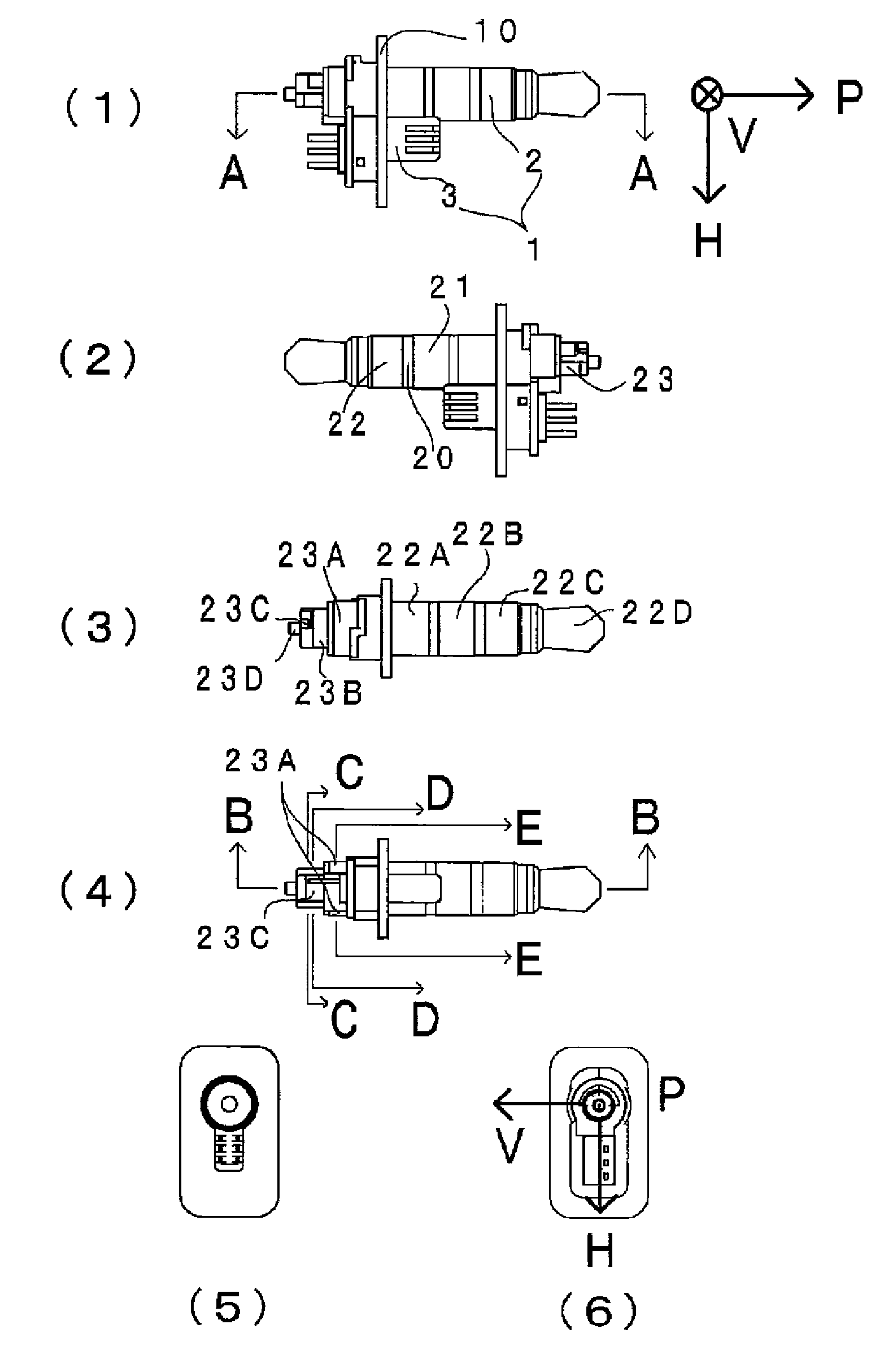
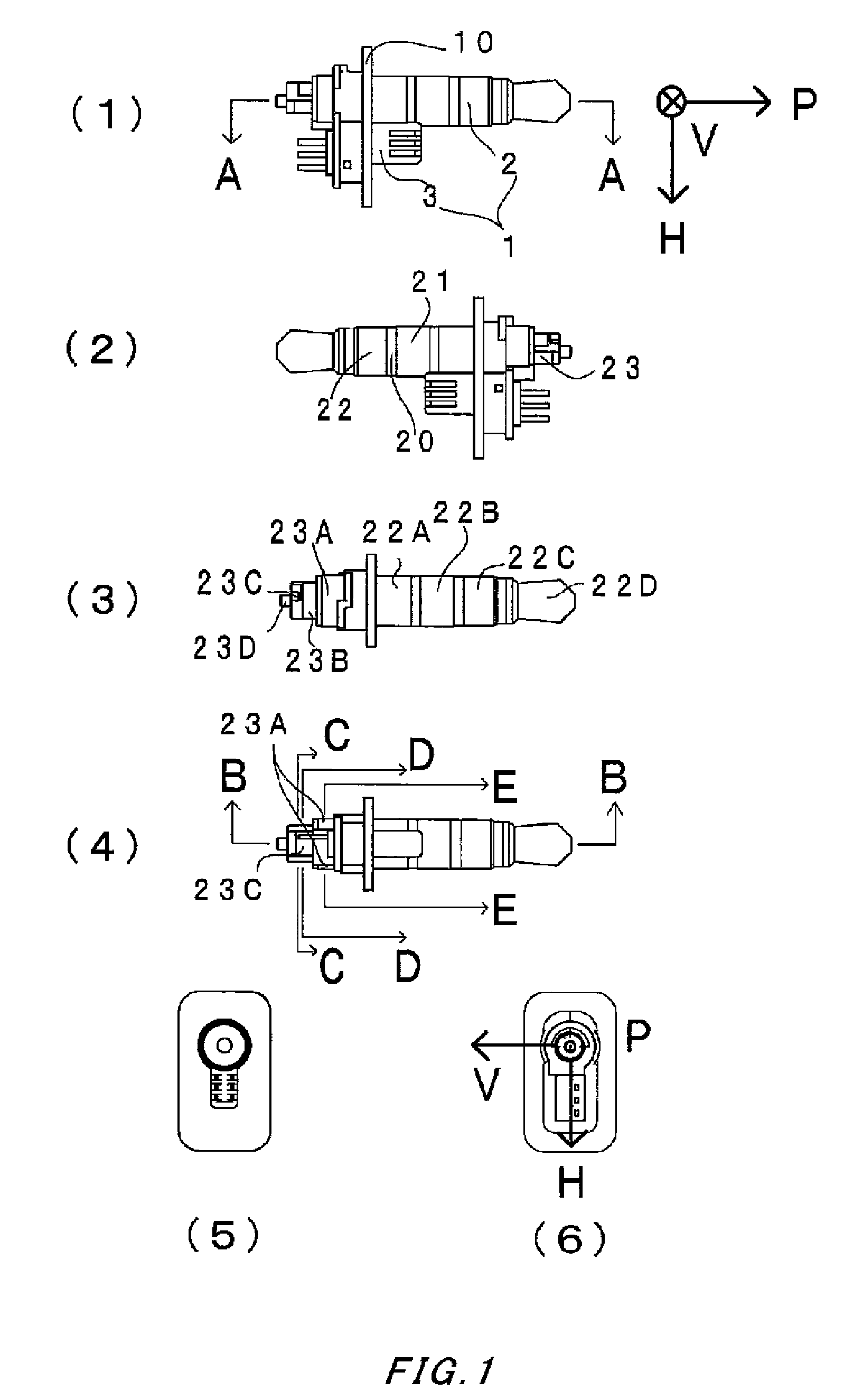
[0068]A plug according to the present invention is disposed in a composite connector 1 including a multi-pole connector 3.

[0069]The composite connector 1 includes: a housing 10 formed of an insulator such as an insulating resin; a plug 2 formed integrally with the housing 10; and the multi-pole connector 3 incorporated with the housing 10. A mating composite connector (not shown) that mates with the composite connector 1 includes a jack (not shown) and a multi-pole socket (not shown). An electronic device connected to the composite connector 1 is connected to an electronic device connected to the mating composite connector by fitting the composite connector 1 into the mating composite connector, i.e., fitting the plug 2 into the jack and fitting the multi-pole connector 3 into the multi-pole socket. The plug 2 includes: a mating electrode group 22 that is disposed on the front side thereof and ...


PUM


Abstract

A plug includes a plug housing and a metal terminal group. The metal terminal group includes a mating electrode group on the first end side thereof and a connection electrode group on the second end side, the mating electrode group including mating electrode sections that are disposed with an insulating resin interposed therebetween and are to be in contact with the contacts of a mating jack, the connection electrode group including connection electrode sections that are disposed with an insulating resin interposed therebetween and are connected to the electrodes of a connection member. The mating electrode sections are disposed coaxially with an axis P of the plug, and at least two of the connection electrode sections are disposed around the axis P so as to surround the axis P side by side.

Description

CROSS REFERENCE TO RELATED APPLICATIONS[0001]The contents of the following Japanese patent application is incorporated herein by reference,[0002]No. 2009-278223 filed on Dec. 8, 2009.BACKGROUND[0003]1. Technical Field[0004]The present invention relates mainly to a connection structure of a single-head plug to be connected to a cable.[0005]2. Description of the Related Art[0006]In conventional single-head plugs to be connected to a cable, the electrodes thereof are directly connected to connection electrode sections extending to the connection area of the plug by, for example, soldering.[0007]For example, in Japanese Patent Application Publication No. 2002-134238, the connection electrode sections of a plug are coaxially arranged in its connection area so as to correspond with the coaxial arrangement of plug electrodes to be connected to the contacts of a jack that mates with the plug. Although not explicitly described, the connection electrode sections are directly soldered to a cab...

Claims


Application Information

Patent Timeline
IPC IPC(8): H01R24/04
CPCH01R24/58H01R2107/00H01R24/66
Inventor AKAIWA, TAKUSHINOZAKI, SUSUMUMATSUDA, TAKESHIKATO, TATSUOKOMURO, MASAJINAKAZAWA, KENJIHATANO, KENJIKIMURA, YOSHITAKA
Owner SMK CORP
Why Eureka
Try Eureka