
Electric motor fuel pump having a reduced length

Inactive Publication Date: 2006-04-27
TI GRP AUTOMOTIVE SYST LLC
View PDF19 Cites 9 Cited by
  • Summary
  • Abstract
  • Description
  • Claims
  • Application Information

AI Technical Summary

Benefits of technology

[0007] Some objects, features and advantages of the present invention include providing a brush-type electric fuel pump assembly that is readily adaptable to various fuel tank and vehicle applications including under-seat applications; has a reduced axial length on the order of 25% reduction in overall length compared to prior art designs; does not require a space-consuming male outlet fitting; does not require space-consuming axially-oriented compression springs; is of relatively simple design and economical manufacture and assembly; is rugged, durable, and reliable; and has a long, useful life in service.

Problems solved by technology

But, current fuel pumps are too axially long to be packaged in such a location.

Method used


Image

  • Electric motor fuel pump having a reduced length
  • Electric motor fuel pump having a reduced length
  • Electric motor fuel pump having a reduced length

Examples


Embodiment Construction

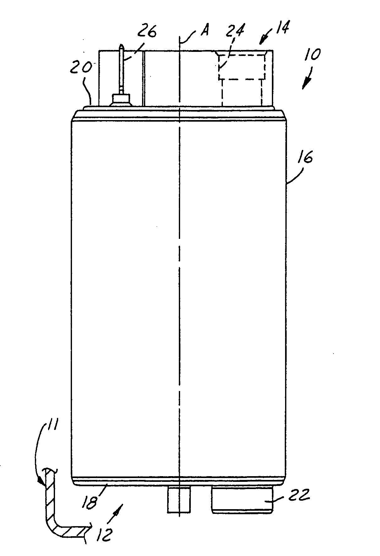
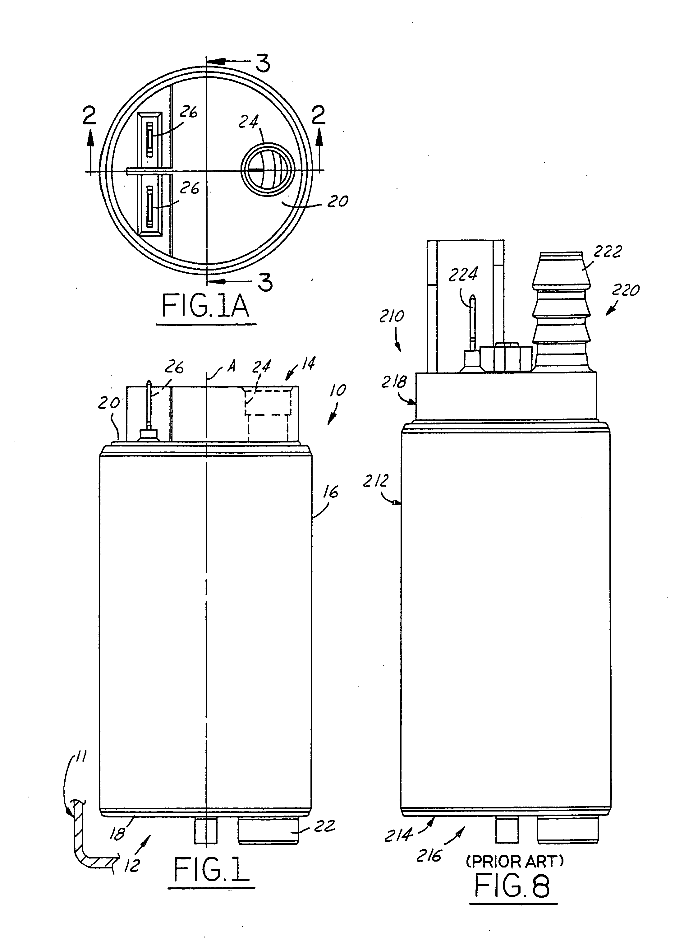
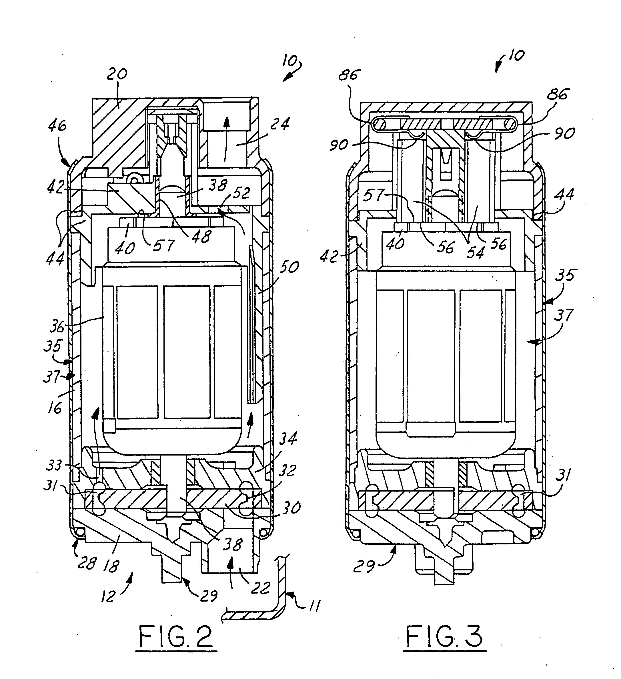
[0019] Referring in detail to the drawings, FIG. 1 illustrates an electric motor and fuel pump assembly 10 that is typically mounted with its longitudinal axis A extending generally vertically in a fuel tank 11 of an automotive vehicle (not shown), with an inlet end 12 positioned adjacent a bottom portion of the fuel tank to pick up fuel and deliver the fuel at a higher pressure through an oppositely disposed outlet end 14. A cylindrical housing sleeve 16 generally defines the longitudinal axis A of the electric motor and fuel pump assembly 10 and connects an inlet cover 18 at the inlet end 12 to an outlet cover 20 at the outlet end 14. The inlet cover 18 includes an inlet port 22 extending axially therefrom for drawing fuel into the electric motor and fuel pump assembly 10.

[0020] As shown in FIGS. 1 and 1A, the outlet cover 20 includes a female outlet port 24 and axially-extending electrical terminal blades 26 molded or assembled thereto. The outlet port 24 is adapted for attachme...


PUM


Abstract

An electric motor and fuel pump assembly with a housing having generally opposed ends with an electric motor within the housing having an armature with an axial commutator adjacent one end of the armature and one end of the housing. A fuel pump is positioned adjacent another end of the housing and the armature and is operably connected to the armature for being driven by the electric motor. A carrier within the housing has guides slidably receiving axially elongate brushes disposed generally parallel to the armature axis with ends contacting the commutator. Each brush is biased generally axially into contact with the commutator by a torsional spring with a coiled body having an axis generally transverse to the axis of the armature to decrease the overall axial length of the pump assembly. Preferably an end cover of the housing overlies and encloses the springs and brushes and preferably has an outlet port laterally offset from the brushes and within the outer periphery of the end cover to further decrease the overall axial length of the fuel pump assembly. Preferably electrical connector blades extend through the end cover and are laterally offset from and axially overlap in electrical connection with the brushes for supplying current to the motor.

Description

FIELD OF THE INVENTION [0001] This invention relates generally to fuel pumps, and more particularly to a fuel pump that is used in a fuel tank and that has an electric motor with brushes. BACKGROUND OF THE INVENTION [0002] Electric motor fuel pumps are widely used to supply fuel to operating internal combustion engines, such as in automotive applications. A fuel pump is typically disposed within a fuel tank and has a lower inlet end for drawing fuel from within the tank and an upper outlet end for outputting drawn fuel under pressure to the engine. Examples of fuel pumps of this general type are illustrated in U.S. Pat. Nos. 5,257,916, and 6,231,318. As shown in FIG. 8, a prior art fuel pump 210 includes a cylindrical metal housing 212 that connects to an inlet cover 214 at a lower inlet end 216 and to an outlet cover 218 at an upper outlet end 220. Although not shown in the figure, there are several components within the housing 212 and between the covers 214, 218. Stacked axially ...

Claims


Application Information

Patent Timeline
IPC IPC(8): F04B35/04F04B17/00
CPCF04B53/22
Inventor GOTTSCHALK, WADE A.KUPERUS, PETER P.
Owner TI GRP AUTOMOTIVE SYST LLC
Learn More