Adaptable lighting system

a technology of adaptable lighting and control unit, which is applied in the direction of lighting apparatus, light sources, instruments, etc., to achieve the effect of self-healing, redundancy, and enhancing functionality

Active Publication Date: 2012-11-29
KONINKLIJKE PHILIPS ELECTRONICS NV
View PDF5 Cites 6 Cited by
  • Summary
  • Abstract
  • Description
  • Claims
  • Application Information

AI Technical Summary

Benefits of technology

[0013]Accordingly, and as discussed above, the lighting system may comprise more than two light sources, e.g. a third light source. Advantages of the inventive method include the possibility to handle also the introduction of further light sources, such as the third light source. The introduction of the third light source into the lighting system, enables the lighting system to automatically adapt the drive signals for each of the light sources, e.g. the first, the second and the third light source, such that essentially the predetermined illumination pattern is achieved, for example by dimming and redirecting the first and the second light source. Such adjustments to the first and the second light source may provide a prolonged lifetime of the first and the second light sources as they possibly do not have to be operated at a level as high as when only the first and the second light sources are present. The self healing feature of the lighting system is further improved, and a redundancy to the system may be provided as possibly essentially the same illumination pattern may be achieved with only two of the three light sources.
[0014]The feature of allowing the introduction of a further light source into the lighting system may also be used in conjunction with “neighborhood profiling”, i.e. one light source is moved from a first lighting system to a second lighting system. As a result of being introduced into the second lighting system, the light source may e.g. automatically adapt and match to the lighting settings (e.g. illumination pattern) of the second lighting system for further enhancing the functionality and redundancy of the second lighting system. The identification and joining of the second lighting system (from the perspective of the light source) may e.g. be provided by listening to network traffic generated by the second lighting system, for example including listening to RF, IR, ultrasound or other signals generated by the second lighting system.

Problems solved by technology

The control of such lighting systems for creating application-specific lighting scenes has conventionally been performed by technicians having certain skills and experience, since controlling of for example brightness, color and saturation parameters is relatively complicated and conventionally requires certain knowledge and skills.

Method used


Image

  • Adaptable lighting system
  • Adaptable lighting system
  • Adaptable lighting system

Examples


Embodiment Construction

[0020]The present invention will be described more fully hereinafter with reference to the accompanying drawings, in which currently preferred embodiments of the invention are shown. This invention may, however, be embodied in many different forms and should not be construed as being limited to the embodiments set forth herein; rather, these embodiments are provided for thoroughness and completeness, and fully convey the scope of the invention to the skilled addressee. Like reference characters refer to like elements throughout.

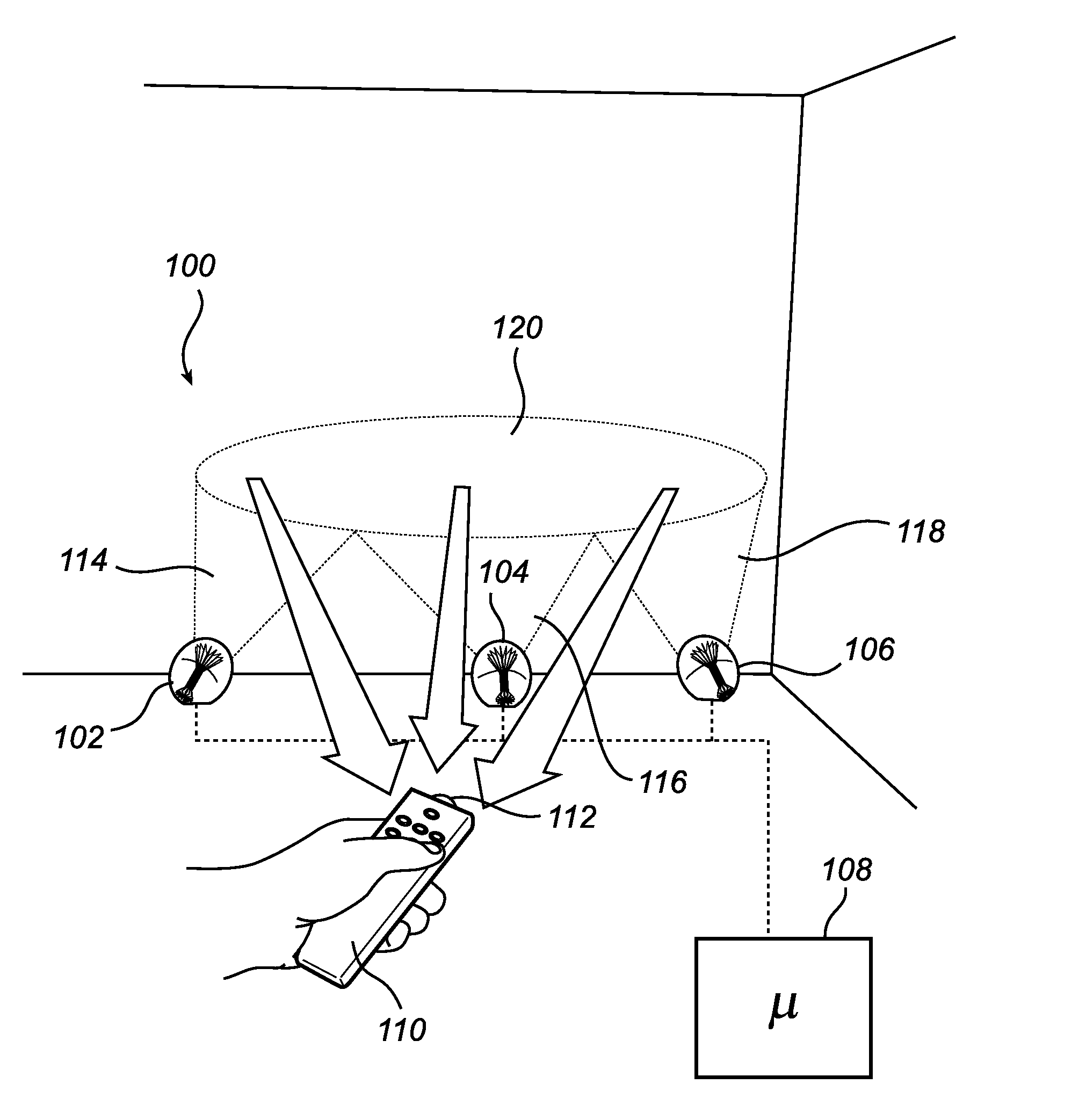
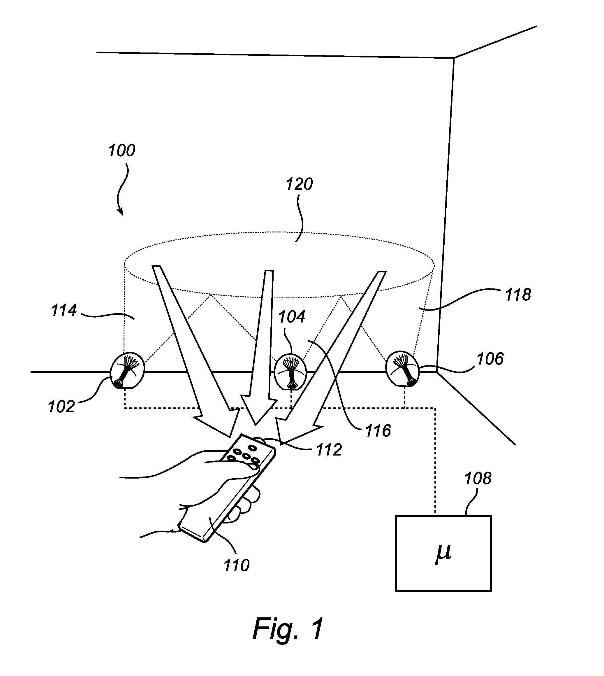
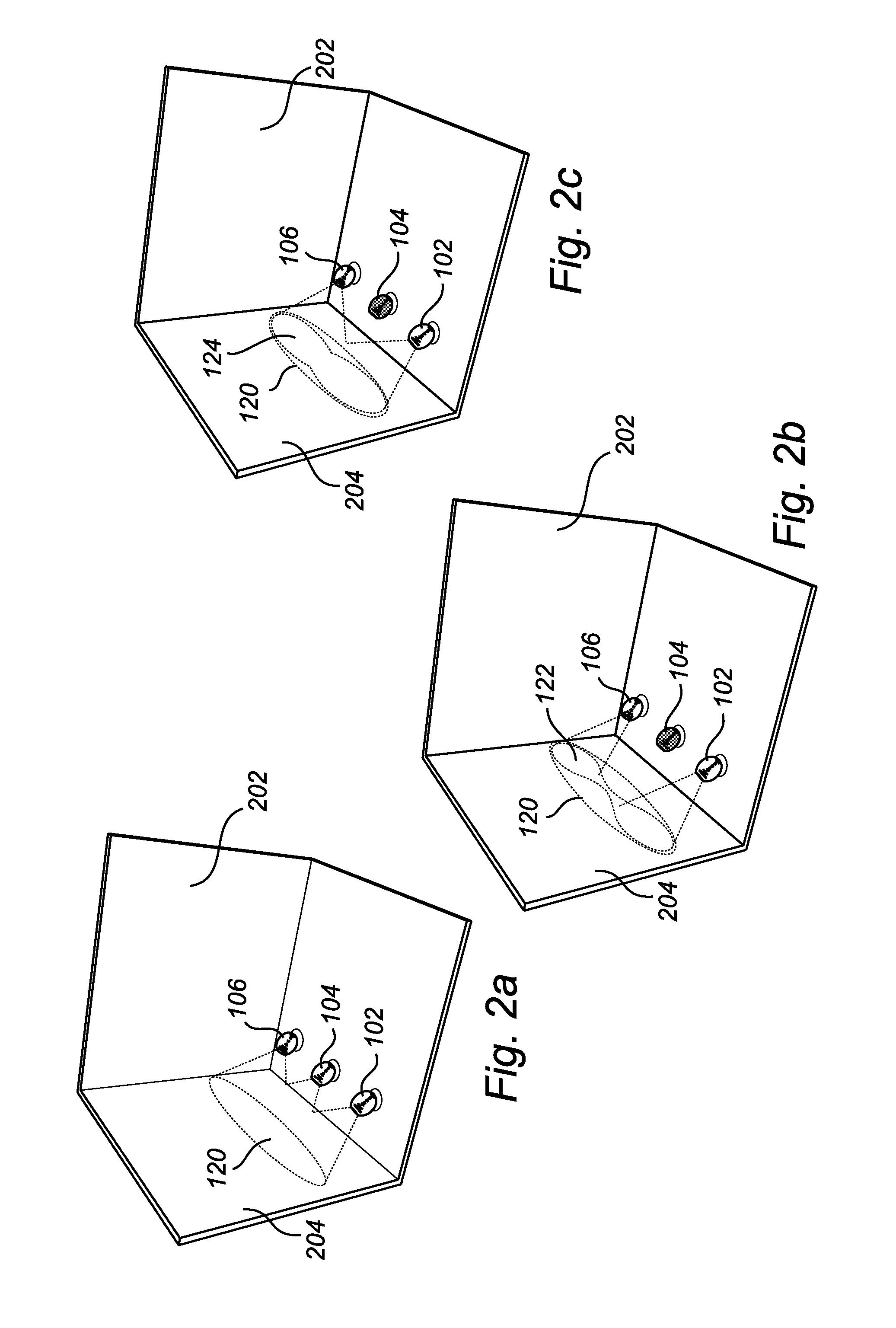
[0021]Referring now to the drawings and to FIG. 1 in particular, there is depicted a lighting system 100 according to a currently preferred embodiment of the invention. The lighting system 100 comprises three light sources 102, 104, 106, each being individually controllable, for example as regards e.g. intensity, color and direction of emitted light. The lighting system 100 further comprises a control unit 108 connected to the light sources 102, 104, 106, for...


PUM


Abstract

The present invention relates to a control unit (108) for a lighting system (100) comprising at least two individually controllable light sources (102, 104), wherein the control unit (108) is connectable to the at least two individually controllable light sources (102, 104) and configured to control the at least two individually controllable light sources (102, 104), wherein the control unit (108) is further configured to control a first lighting system configuration comprising the at least two individually controllable light sources (102, 104) so as to cause it to emit a first illumination pattern (120) provided jointly by the at least two light sources (102, 104) of the first lighting system configuration, detect and store an initial set of illumination parameters being indicative of the first illumination pattern (120), determine a subsequent set of illumination parameters being indicative of a second illumination pattern (122) provided by a second lighting system configuration comprising individually controllable light sources (102, 106), the second lighting system configuration being different from the first lighting system configuration, and control, in dependence on the initial set and the subsequent set of illumination parameters, the second lighting system configuration so as to cause it to emit a third illumination pattern (124), the third illumination pattern (124) being an approximation of the first illumination pattern (120). The present invention provides advantages in respect of e.g. automatic “healing” of the lighting system (100), for example in the case where a light source (102, 104) of the lighting system (100) fails or is only capable of providing less than the normal rated light output.

Description

TECHNICAL FIELD[0001]The present invention relates to a control unit for an adaptable lighting system, specifically a lighting system being at least partly adaptable to a change of illumination pattern for portions of the lighting system. The invention also relates to a corresponding method of controlling a lighting system. The invention further relates to a lighting system comprising such a control unit.BACKGROUND OF THE INVENTION[0002]At present, color adjustable light sources, for example light emitting diodes, combining red, green and blue light to achieve for example white light, are increasingly being used in for example household and commercially available lighting systems. The control of such lighting systems for creating application-specific lighting scenes has conventionally been performed by technicians having certain skills and experience, since controlling of for example brightness, color and saturation parameters is relatively complicated and conventionally requires ce...

Claims


Application Information

Patent Timeline
Patent Type & Authority Applications(United States)
IPC IPC(8): H05B37/02
CPCH05B37/029H05B47/155
Inventor SCHENK, TIM CORNEEL WILHELMUSBEIJ, MARCELYIANNI, GEORGE FREDERIC FREDERICBROEKSTEEG, GERARDUS HENRICUS ADRIANUS JOHANNESVINKENVLEUGEL, LUCIUS THEODORUSFERI, LORENZO
Owner KONINKLIJKE PHILIPS ELECTRONICS NV
Why Eureka
Try Eureka