Eureka AIR delivers breakthrough ideas for toughest innovation challenges, trusted by R&D personnel around the world.

Test socket with a rapidly detachable electrical connection module

a technology of electrical connection module and test socket, which is applied in the field of test socket, can solve the problems of reducing test efficiency, losing elasticity and electrical characteristic, and dirty electrical conductors, and achieve the effect of high test efficiency

Inactive Publication Date: 2012-11-29
TEK CROWN TECH
View PDF3 Cites 8 Cited by
  • Summary
  • Abstract
  • Description
  • Claims
  • Application Information

AI Technical Summary

Benefits of technology

[0008]The main object of the present invention is to provide a test socket with a rapidly detachable electrical connection module for high test efficiency.
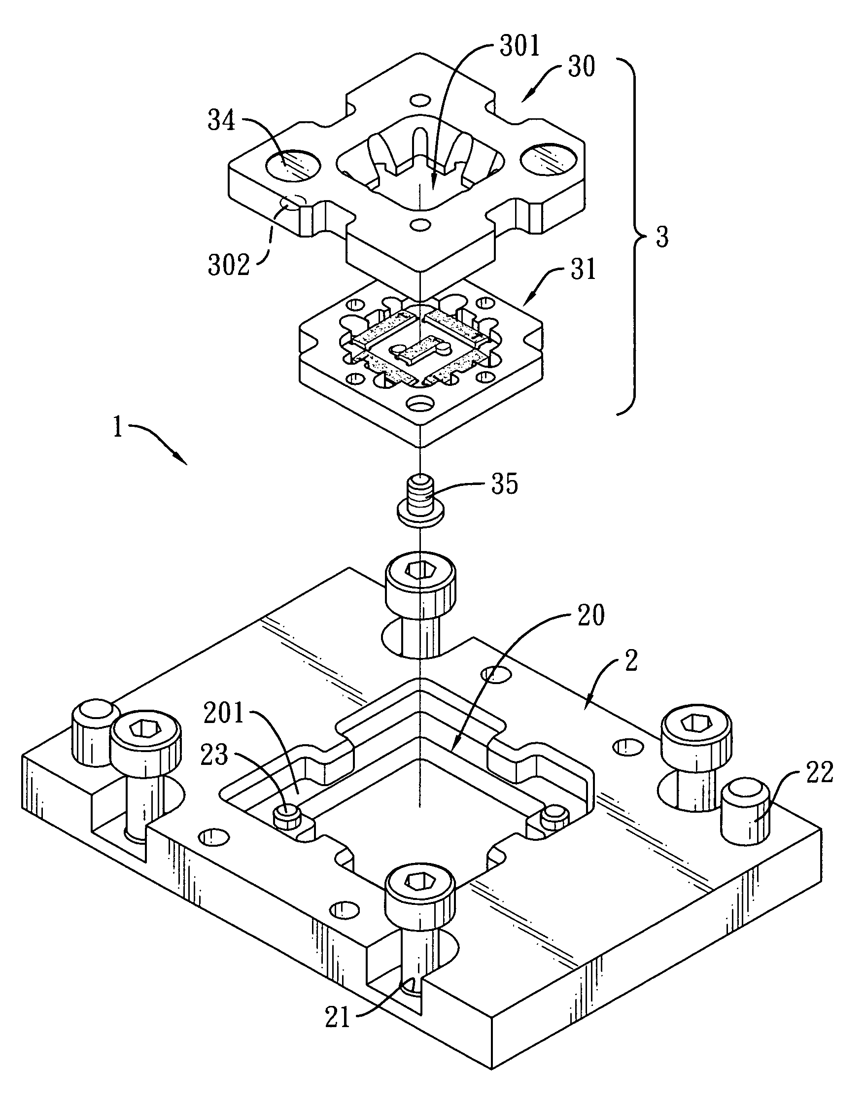
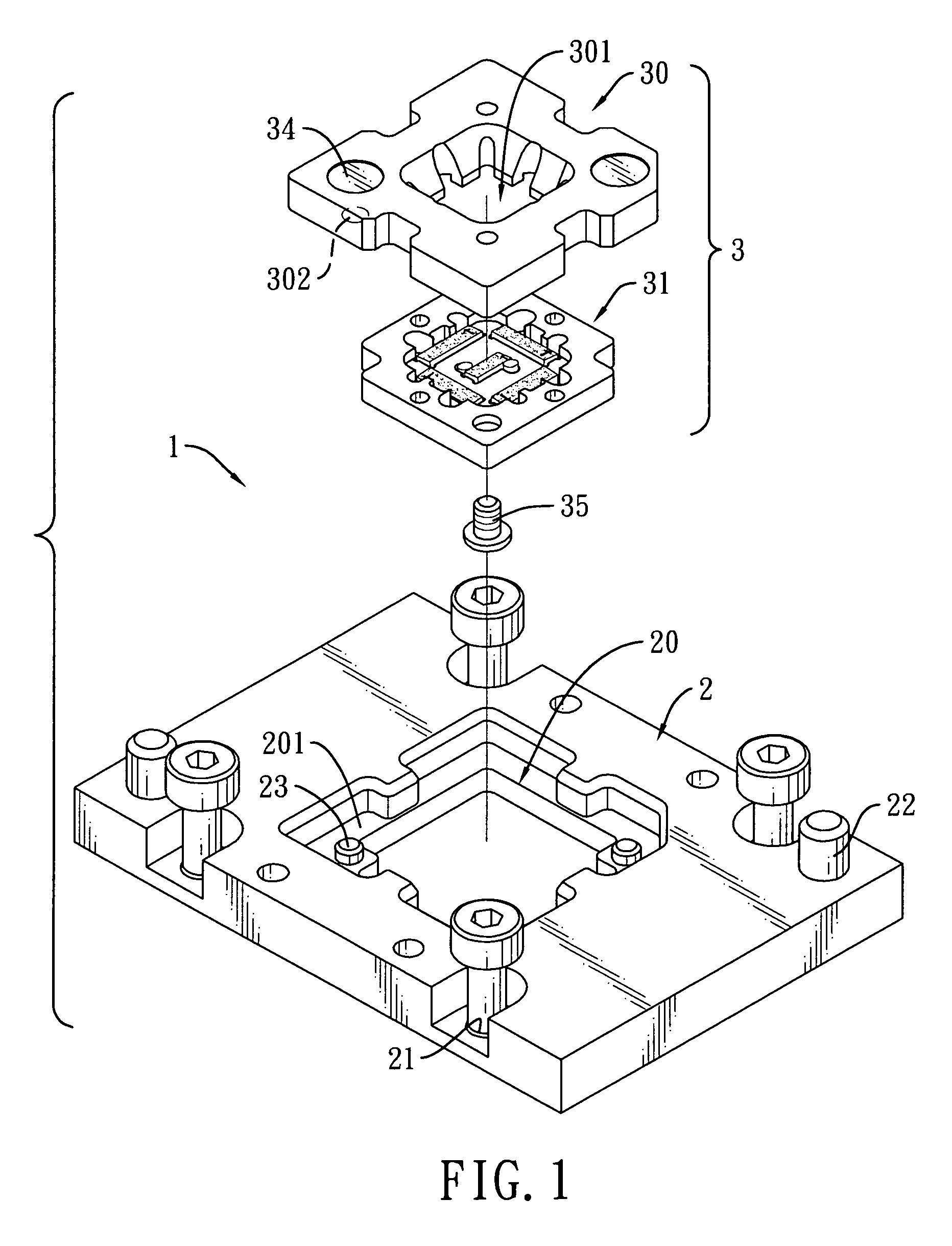
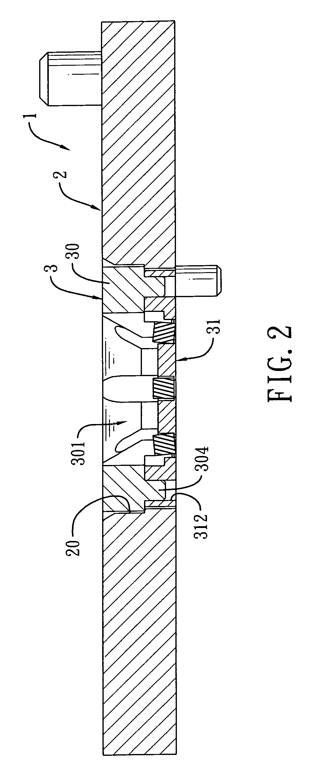
[0009]To achieve the foregoing objective, the test socket in accordance with the present invention comprises a test base and at least one electrical connection module. The test base includes a top surface, a bottom surface and a mounting hole. The mounting hole is formed through the test base and extends from the top surface to the bottom surface of the test base. The at least one electrical connection module is detachably mounted in the test base and each one of the at least one electrical connection module includes a frame and an electrically conducting element. The frame is detachably mounted in the mounting hole of the test base and has a top surface, a bottom surface and a receiving hole. The receiving hole is formed through the frame and extends from the top surface to the bottom surface of the frame for receiving and testing an IC. The electrically conducting element is detachably mounted on the bottom of the frame. After long time of use, the ineffective electrical connection module or electrically conducting element thereof can be rapidly and easily replaced with a new or an effective one by directly detaching the electrical connection module from the test base. Therefore, idle time or dead time of a test apparatus is shortened and test efficiency is enhanced.

Problems solved by technology

The electrically conducting element will become dirty and lose its elasticity and electrical characteristic after being repeatedly subjected to the pressing forces.
In general, the test apparatus must be stopped for tens of minutes each replacement time and therefore test efficiency is reduced.

Method used


Image

  • Test socket with a rapidly detachable electrical connection module
  • Test socket with a rapidly detachable electrical connection module
  • Test socket with a rapidly detachable electrical connection module

Examples


Embodiment Construction

[0021]With reference to FIG. 1, a test socket 1 in accordance with the present invention comprises a test base 2 and at least one electrical connection module 3.

[0022]The test base 2 includes a top surface, a bottom surface, a mounting hole 20, multiple locating holes 21, multiple connecting columns 22 and at least one positioning pin 23. The mounting hole 20 is formed through the test base 2, extends from the top surface to the bottom surface of the test base 2 and has an upper portion, a lower portion and a step surface 201. A hole diameter of the upper portion is larger than a hole diameter of the lower portion. The step surface 201 is formed between the upper portion and the lower portion. The locating holes 21 are respectively formed through the test base 2 around the mounting hole 20. Screws are mounted through the locating holes 21 and a load board 4 to fix the test base 2 on the load board 4 (with reference to FIG. 7). The connecting columns 22 respectively protrude from the...


PUM


Abstract

A test socket includes a test base and at least one electrical connection module. The at least one electrical connection module is detachably mounted in the test base and each one of the at least one electrical connection module has a frame and an electrically conducting element. The frame has a receiving hole for receiving and testing an IC. The electrically conducting element is detachably mounted on a bottom of the frame. After long time of use, the ineffective electrical connection module or electrically conducting element thereof can be rapidly and easily replaced with a new or an effective one by directly detaching the electrical connection module from the test base. Therefore, idle time or dead time of test apparatuses is shortened and test efficiency is enhanced.

Description

BACKGROUND OF THE INVENTION[0001]1. Field of the Invention[0002]The present invention relates to a test socket, and more particularly to a test socket with a rapidly detachable electrical connection module.[0003]2. Description of the Prior Arts[0004]Test sockets mounted on manual or automated test apparatuses are used for receiving and testing integrated circuit (IC). A conventional test socket comprises a test base and an electrically conducting element. The test base includes a receiving hole for receiving and testing an IC. The electrically conducting element is mounted on a bottom of the test base and the test base is then screwed to a load board of a test apparatus to hold the electrically conducting element. The electrically conducting element serves as an electrically conducting medium between the IC and the load board of the test apparatus and includes multiple input and output terminals respectively electrically connected to corresponding contact pads of the load board.[000...

Claims


Application Information

Patent Timeline
Patent Type & Authority Applications(United States)
IPC IPC(8): G01R31/00
CPCG01R1/0483G01R1/0466
Inventor WU, MIKE
Owner TEK CROWN TECH
Why Eureka
Eureka Blog
Learn More