Three-dimensional imaging system using a single lens system

a three-dimensional imaging and single lens technology, applied in the field of stereoscopic imaging, can solve the problems of stilted motion and unwanted video conten

Inactive Publication Date: 2012-11-29
BATTELLE MEMORIAL INST
View PDF2 Cites 30 Cited by
  • Summary
  • Abstract
  • Description
  • Claims
  • Application Information

AI Technical Summary

Benefits of technology

[0008]The third polarizing structure may be space

Problems solved by technology

The slowed update rate can lead to unwan

Method used


Image

  • Three-dimensional imaging system using a single lens system
  • Three-dimensional imaging system using a single lens system
  • Three-dimensional imaging system using a single lens system

Examples


Embodiment Construction

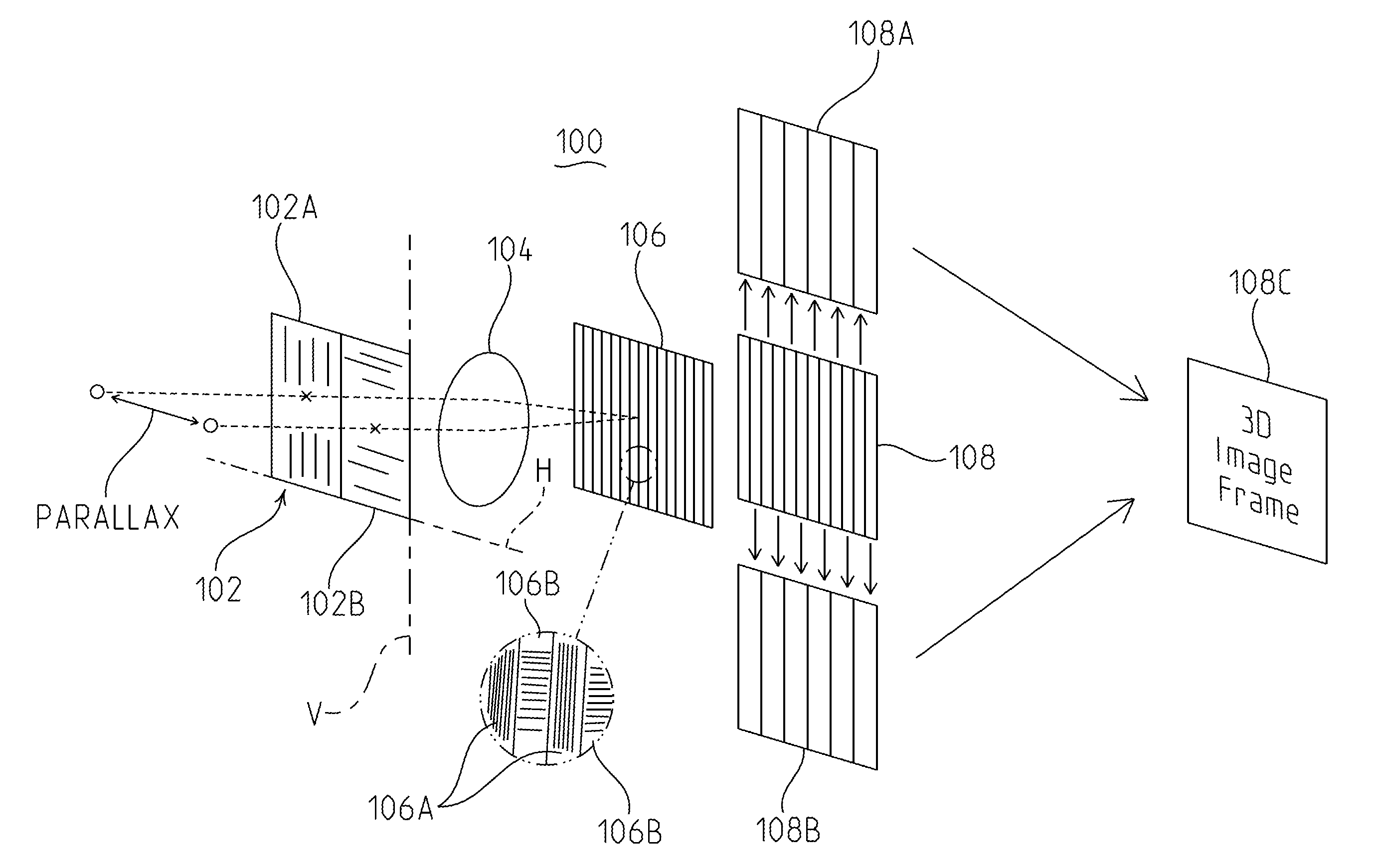
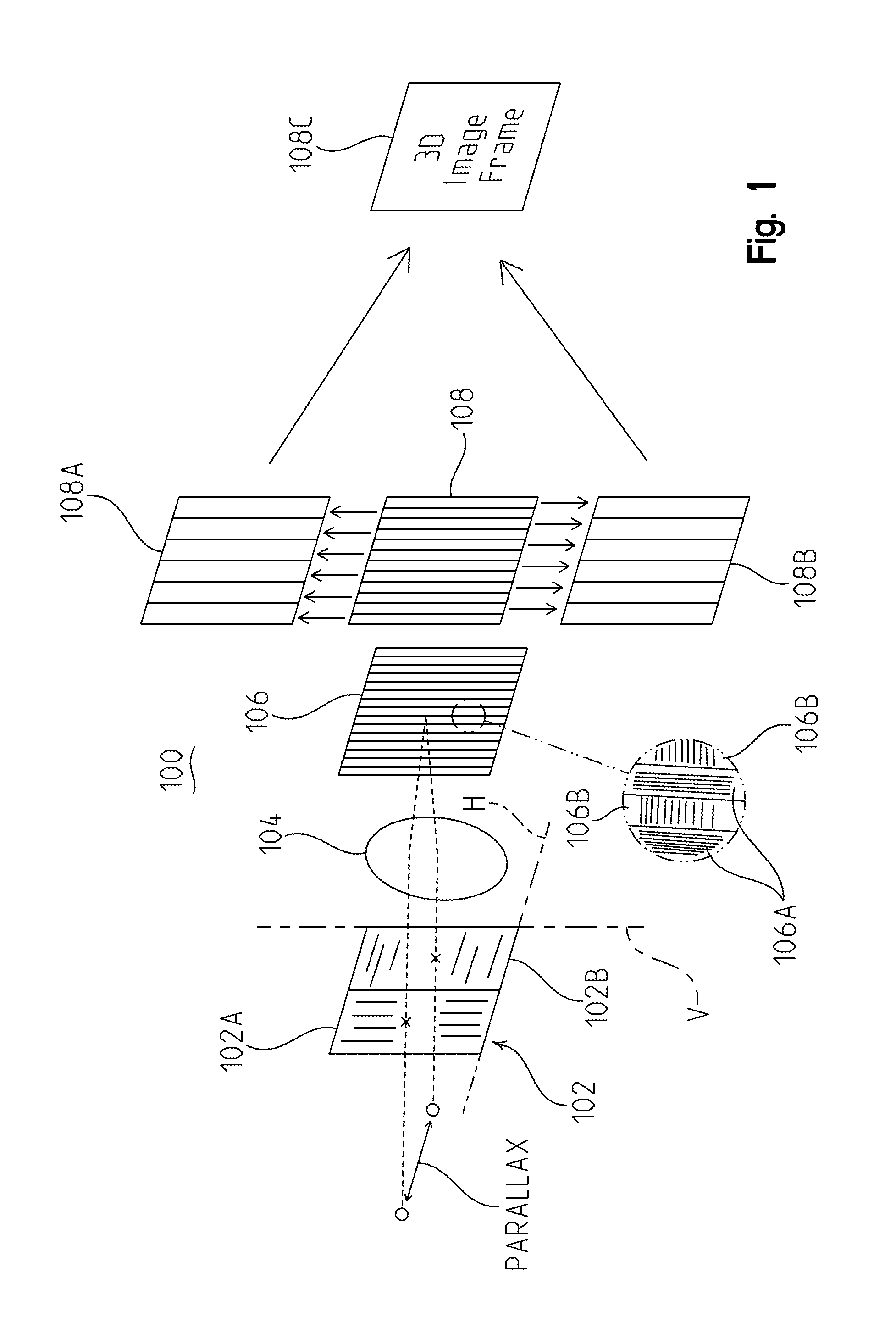
[0017]In the imaging system of the present application, parallactic information is passively captured using a single electronic imaging device, such as a CCD or a CMOS array element, and a single lens system in combination with polarizing structures. More particularly, an input polarizer is placed in front of the lens system. Two input polarizers or a single polarizer divided into two different polarizing portions, each being about half of the single polarizer, can be used. Light entering a first polarizer or first side of a single polarizer, for example the left side, is polarized into a first axis, for example the vertical axis. Light entering a second polarizer or second side of a single polarizer, for example the right side, is polarized into a second axis, for example the horizontal axis.

[0018]Additional polarizing structure is placed between the single lens system and an imaging device. This third or interleaving polarizing structure is made up of sections of polarizers that h...


PUM


Abstract

The passive imaging system of the present application includes first and second input polarizers on the light receiving side of a light receiving lens. A first half of the split polarizer performs vertical polarization of incoming light while the second half of the split polarizer performs horizontal polarization of the incoming light. The input polarizing structure provides parallax to accomplish 3D imaging. A third or interleaving polarizer is provided between the lens and an imaging device and is adjacent to and closely spaced from (<10 microns) the image plane of the device. The interleaving polarizer is sectional so that alternating sections, along the direction of parallax created by the input polarizer(s), pass vertically and horizontally polarized light. The resulting image frame formed at the image plane of the imager is similarly sectional so that sections of the image alternate between vertically polarized light and horizontally polarized light, e.g., for example the odd sections of the image are images of vertical polarized light (received from the left side) and even sections of the image are images of horizontally polarized light (received from the right side). Once an image frame has been captured, it is divided into two parallactic image frames, one of vertically polarized light imaged from the left side and one of horizontally polarized light imaged from the right side. The two resulting frames are combined to form a 3D image.

Description

TECHNICAL FIELD[0001]The present invention relates in general to stereoscopic imaging for producing three-dimensional (3D) video signals and, more particularly, to a passive image pickup device and imaging system that generates three-dimensional signals for video presentation using polarizers and a single lens system.BACKGROUND ART[0002]Typical single lens three-dimensional imaging systems use active devices, such as mechanical choppers, electro-optic switching elements or the like. The active devices are used to selectively pass or block portions of incoming light to create parallactic information such as that sensed by horizontally spaced human eyes. The active devices move to a first position to pass a first portion of received light and block a second to create a first image frame as it would be viewed from a first point, such as the left eye. The active devices then move to a second position to pass a second portion of received light and block the first to create a second image...

Claims


Application Information

Patent Timeline
IPC IPC(8): H04N13/02
CPCH04N13/0225G02B27/26G02B30/25H04N13/225
Inventor LAUDO, JOHN S.
Owner BATTELLE MEMORIAL INST
Why Eureka
Try Eureka