
Paper binder

a paper binder and paper binder technology, applied in the field of paper binder, can solve the problems of troublesome task of removing staples from bound paper sheets, risk of staples piercing fingers, etc., and achieve the effect of appropriate and convenient paper-binding process

Inactive Publication Date: 2012-11-29
PLUS CORP
View PDF3 Cites 2 Cited by
  • Summary
  • Abstract
  • Description
  • Claims
  • Application Information

AI Technical Summary

Benefits of technology

The present invention provides a paper binder that can easily and appropriately bind multiple paper sheets without using any binding material. The binder includes a punch blade, an incising blade, a base, a mounting base, an insertion part, a rotation mechanism, an insertion part, a pressing table, a support base, and a handle. The binder can pinch the paper sheets and form strips and incision by pressing the blade against the paper sheets. The binder can be brought close together to perform the binding process on the paper sheets. The technical effects of the invention include easy and appropriate performance of the paper-binding process and efficient binding of multiple paper sheets.

Problems solved by technology

Staplers have the advantage of allowing paper sheets to be bounded with a simple operation, but on the other hand, there are hazards as well as inconveniences when using a shredder.
That is, with staplers, there is a risk that a staple may pierce the finger, etc. of the user.
Moreover, the task of removing a staple from bound paper sheets is troublesome.
Moreover, there is a risk that the user may fail to see a staple that has been removed from paper sheets.
Furthermore, the user may accidentally insert paper sheets bound with a staple into a shredder or an ADF (Auto Document Feeder) of a copying machine, etc.
Such accidents may cause breakdowns of the shredder or ADF.
However, such staplers have the problem that the refilling or replacement of paste is difficult.
Moreover, it is difficult to provide a configuration by which the adhesive strength between the paper sheets bound by the paste is increased while the application of the paste can be performed smoothly.
As described above, staplers have various problems.
That is, the binding parts of the paper sheets are punched to form ligulate strips and then folded over, and therefore, after binding, the binding parts cannot be browsed.
With regard to this point, with a conventional paper binder such as that disclosed in Patent Document 2 or Patent Document 3, it is not possible to confirm the paper-binding part during the paper-binding process.
However, this type of operation is troublesome and difficult.
Moreover, there is the risk that the paper-binding process may not be performed accurately.
Furthermore, in the paper-binding process of a conventional paper binder, there is the risk of making it difficult to browse characters, etc. shown on the paper-binding part, such as the edge part of the paper sheets.
In particular, if the paper-binding process is performed on a corner part or the top or bottom edges of the paper sheets and information such as the date of printing, the number of pages, or the publisher can no longer be confirmed, this may create problems for browsing the paper sheets.

Method used


Image

  • Paper binder
  • Paper binder
  • Paper binder

Examples


Embodiment Construction

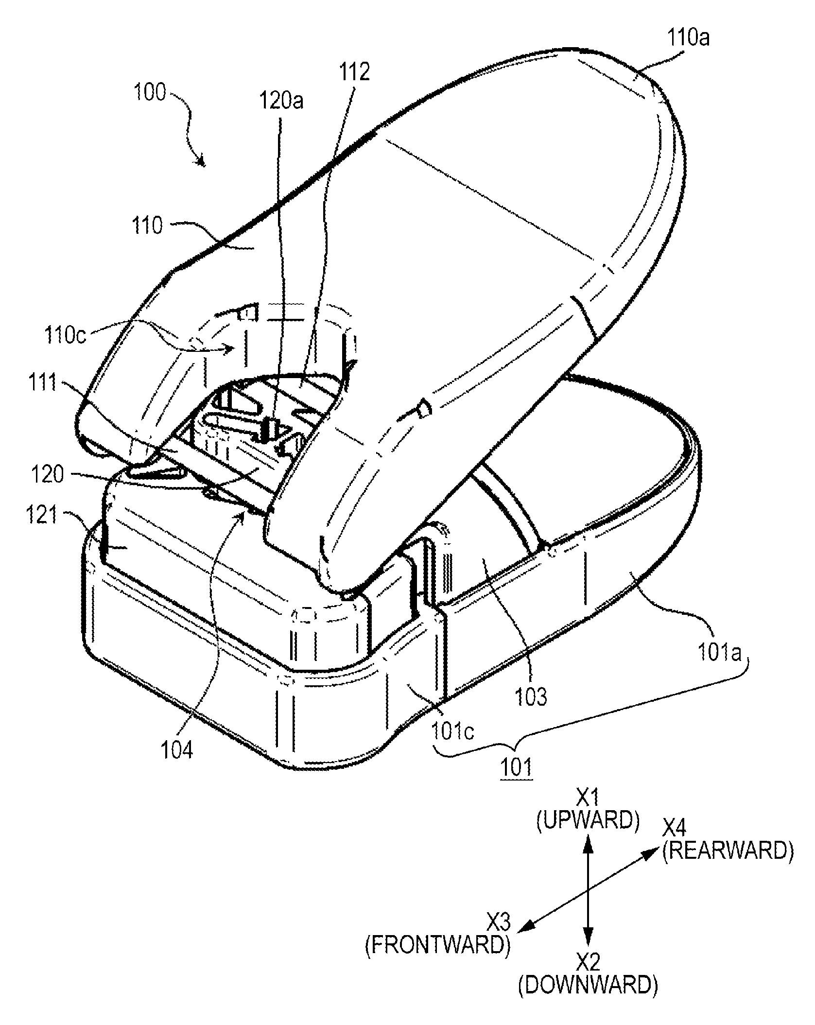
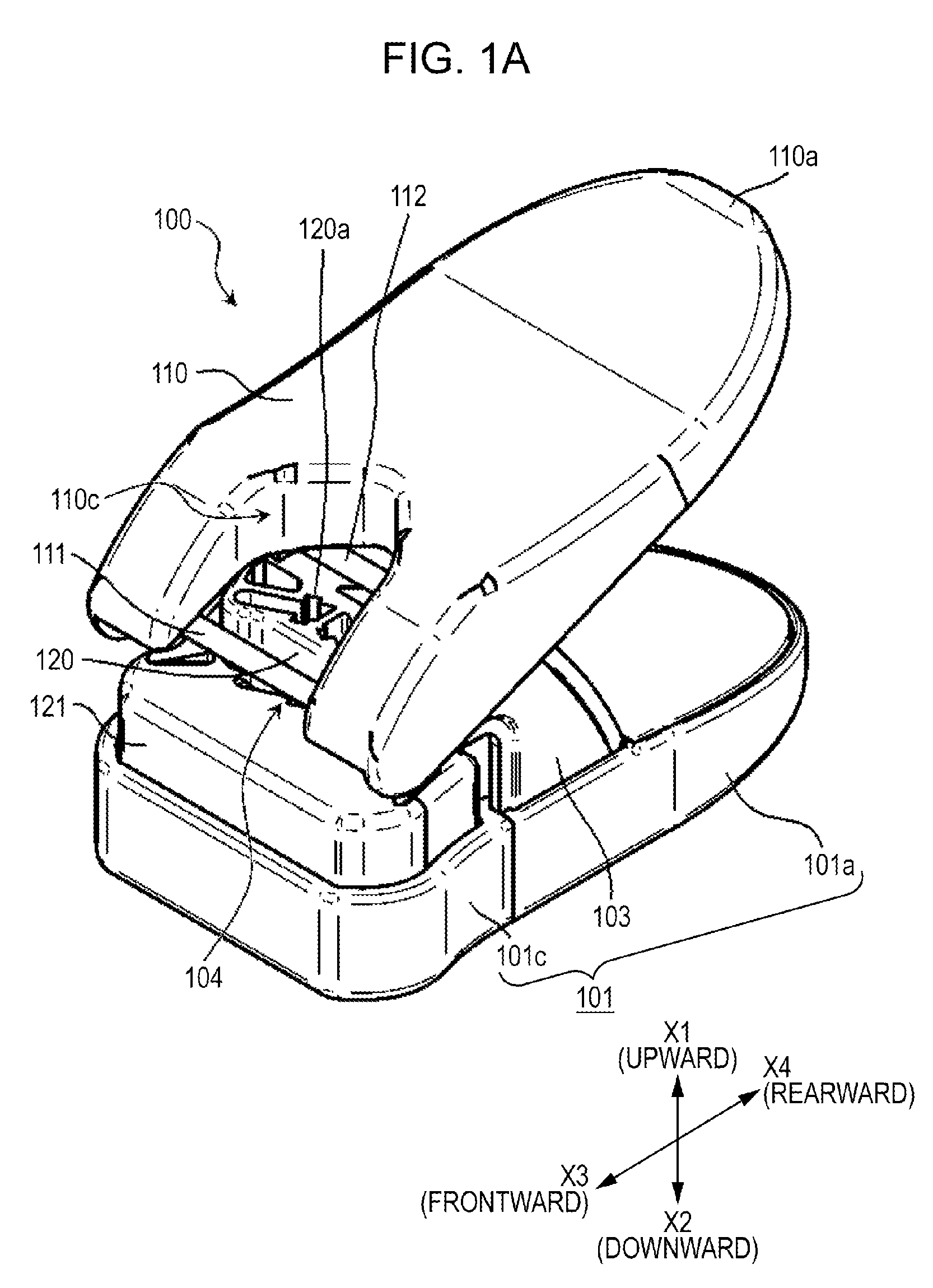
[0047]The following is a description of one example of the present embodiment, with reference to FIGS. 1A-16. To ensure the clarity of the diagrams, in these diagrams, the paper sheets being bound are omitted.

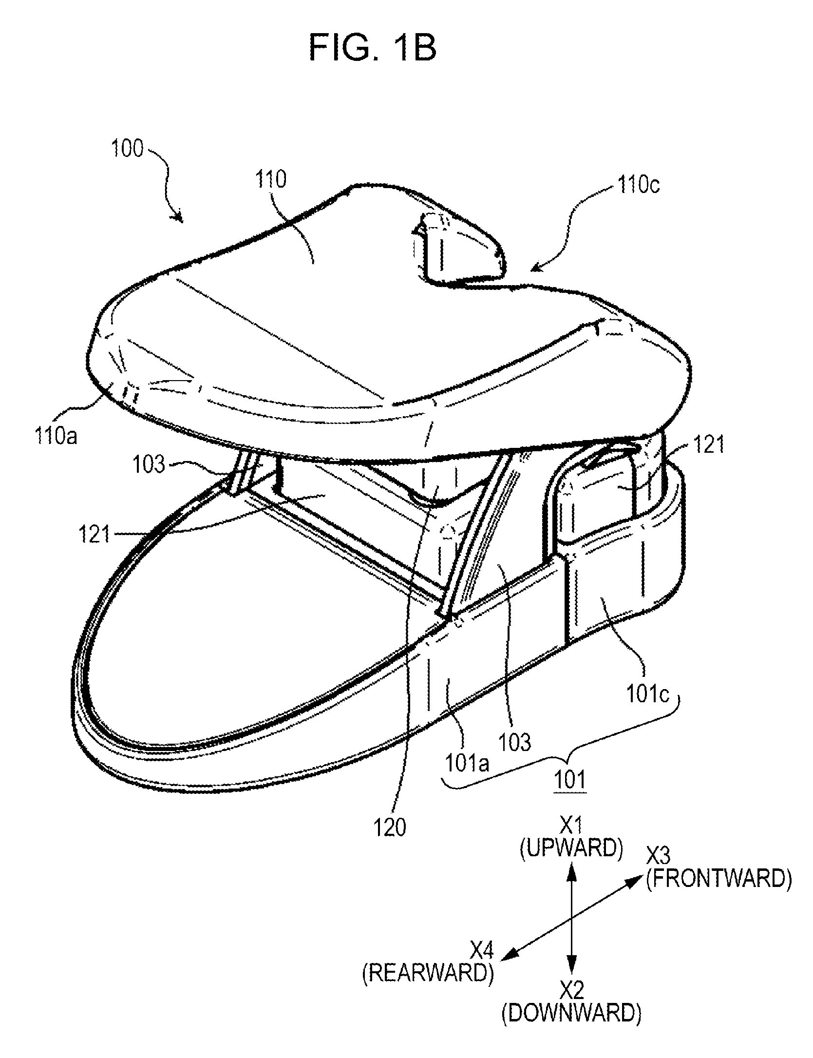
[0048]An overview of the overall configuration of a paper binder 100 according to the present embodiment is described with reference to FIG. 1A, FIG. 1B, and FIG. 2. FIG. 1A is a schematic perspective view of the outer shape of the paper binder 100 viewed from the side of the insertion slot for paper sheets. FIG. 1B is a schematic perspective view of the paper binder 100 viewed from the side opposite to FIG. 1A. FIG. 2 is a schematic exploded perspective view showing the configuration of each part and an overview of the connections between each part in the paper binder 100. The paper binder 100 punches holes in one part of paper sheets using a pair of punch blades (123c; FIG. 2) without cutting away the part from the paper sheet. As a result, first, ligulate (or square-shaped) ...


PUM


Abstract

The purpose of the present invention is to enable multiple paper sheets to be bound without using a binding material such as staples, and to enable the binding process to be performed appropriately and easily on paper sheets that are to be browsed. The configuration is one in which the hole-punching direction and the cutting direction are toward the handle, and the hole-punched part is visible during the binding process via a window portion. Consequently, it is possible to perform the binding process appropriately and easily on paper sheets that are to be browsed. Furthermore, because the multiple sheets are bound by a strip, it is possible to bind multiple paper sheets without using a binding material.

Description

CROSS-REFERENCE TO RELATED APPLICATIONS[0001]This application is based upon and claims the benefit of priority from Japanese Patent Applications No. 2010-014860, filed Jan. 26, 2010; the entire contents of all of which are incorporated herein by reference.FIELD[0002]Embodiments of the present invention relate to a paper binder that is able to punch holes into multiple paper sheets and bind them together. In particular, the present invention is related to technology that binds paper sheets using ligulate strips formed by punching holes into the paper sheets, without using staples (metal pins used for staplers) used in staplers, etc. or adhesive paste.BACKGROUND[0003]Generally, as a binding tool for binding multiple paper sheets, a stapler is used. A stapler is an instrument that is able to cause the front ends of a staple to penetrate paper sheets by pinching and pressing against the paper sheets, and then passing pins through the through-holes and fastening the paper sheets together...

Claims


Application Information

Patent Timeline
Patent Type & Authority Applications(United States)
IPC IPC(8): B42B5/00
CPCB26F1/22B42D1/004B42B5/00B26F1/36
Inventor WU, XIAO DONG
Owner PLUS CORP
Learn More