
Automatic return syringe with ventilation paths for air and suction ports

a return syringe and air-return technology, which is applied in the field of automatic return syringes, can solve the problems of inability to perform continuous air supply, water supply or suction, and difficulty in use of endoscopes, so as to improve portability, simplify the device, and improve the effect of portability

Inactive Publication Date: 2013-03-26
FUJIFILM CORP
View PDF29 Cites 1 Cited by
  • Summary
  • Abstract
  • Description
  • Claims
  • Application Information

AI Technical Summary

Benefits of technology

Enables continuous and versatile air / water supply or suction without supply amount limitations, simplifying device configurations and enhancing portability and convenience for endoscope use in various settings.

Problems solved by technology

However, if the air / water supply, suction are carried out with the prior-art endoscope device, the pump 8 for air / water supply (device) and the pump 10 for suction are needed as mentioned above, and there is a problem of a difficulty in use of the endoscope at facilities where the pump 8 for air / water supply or the pump 10 for suction is not arranged.
Also, a syringe used in general can perform any one of air supply, water supply or suction once by pushing and operating the piston manually but cannot perform continuous air supply, water supply or suction without limitation on supply amount.

Method used


Image

  • Automatic return syringe with ventilation paths for air and suction ports
  • Automatic return syringe with ventilation paths for air and suction ports
  • Automatic return syringe with ventilation paths for air and suction ports

Examples


first embodiment

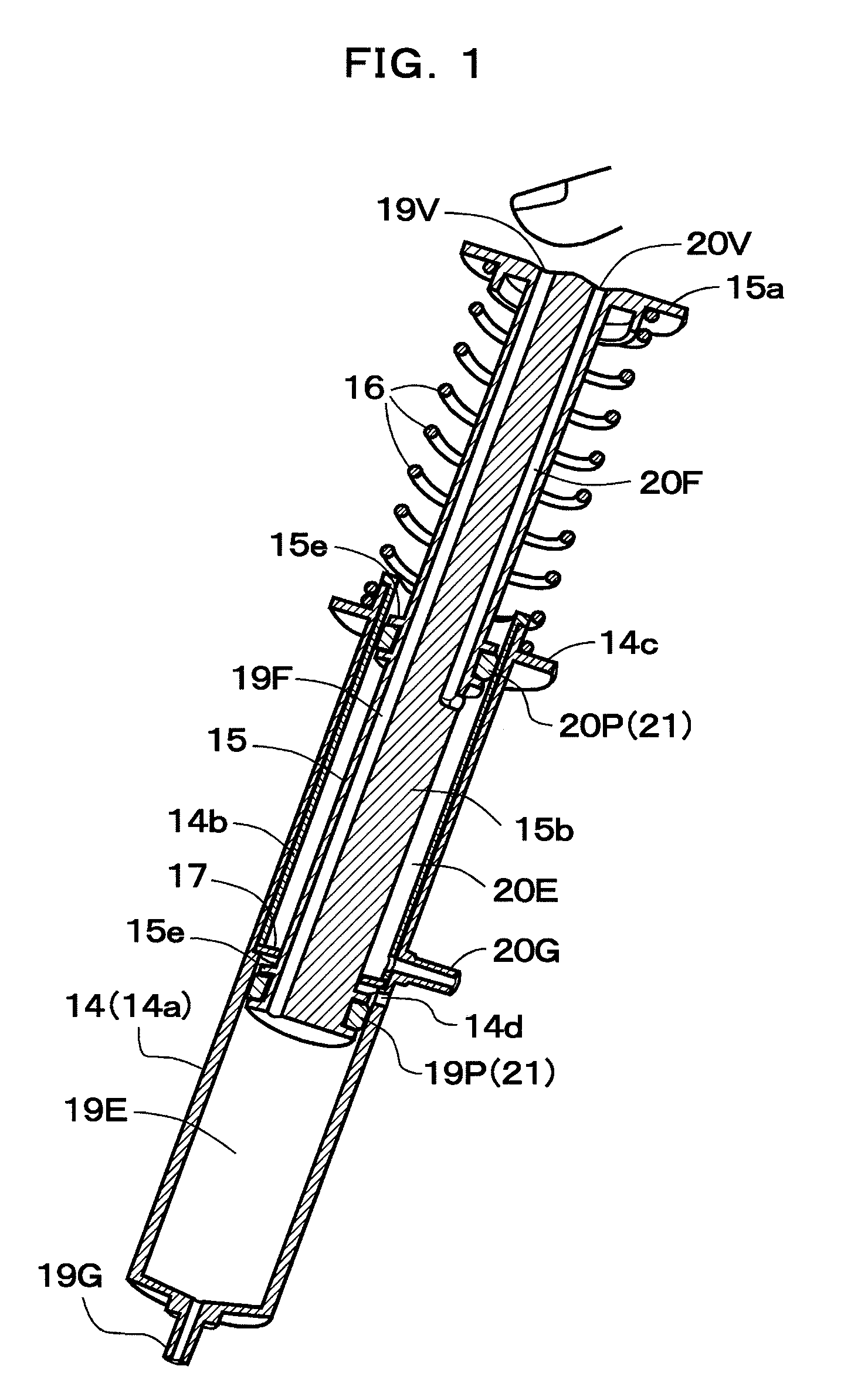
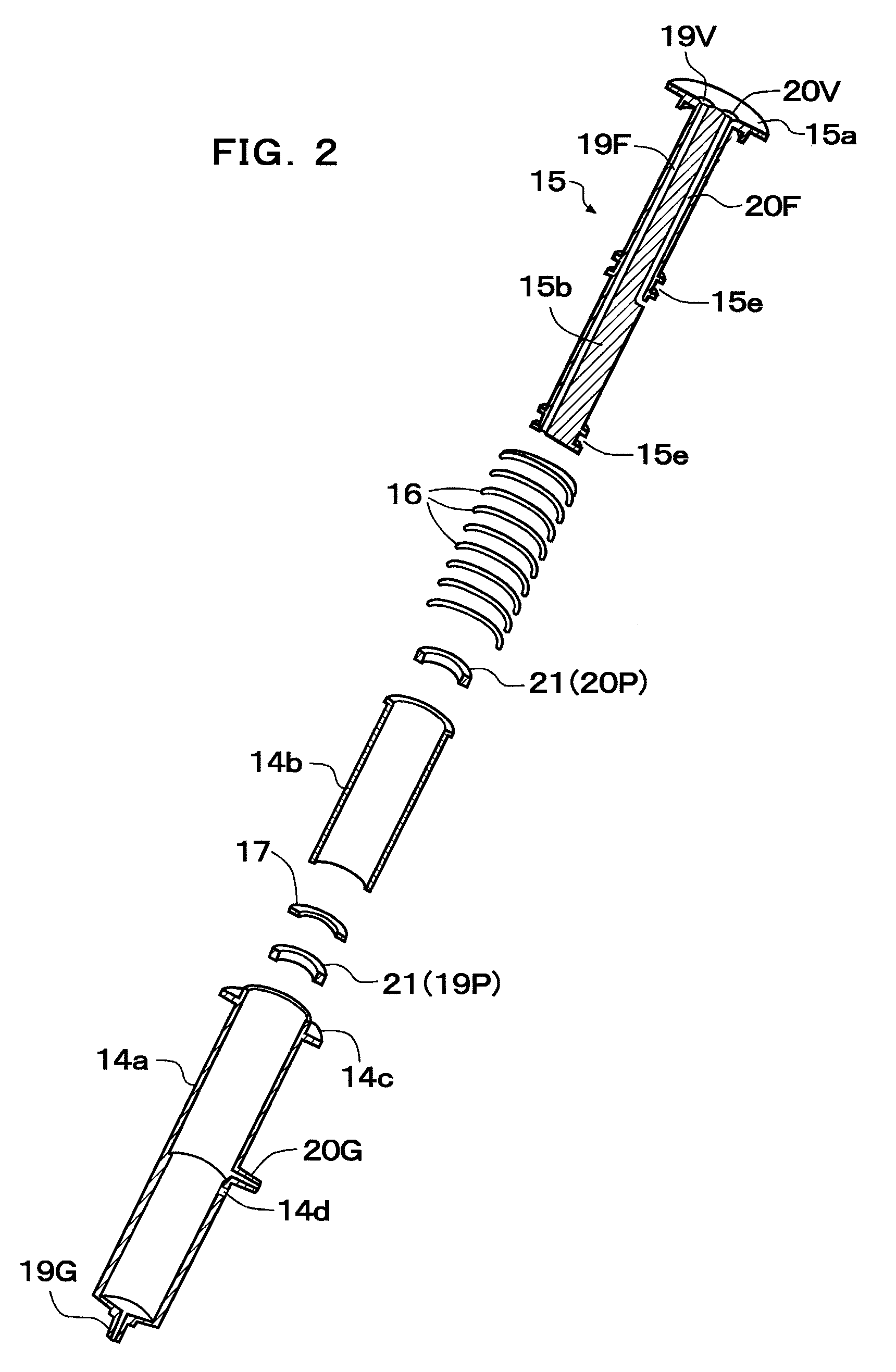
[0055]FIGS. 1 to 4 show a configuration of an automatic return syringe according to a first embodiment, and in this first embodiment, two syringe space portions are arranged in series. As shown in FIG. 1, a syringe in the embodiment comprises a cylindrically-shaped cylindrical body 14, a piston body (slider) 15, and a spring 16, and in the cylindrical body 14, a short second cylindrical body 14b is mounted on a first cylindrical body 14a so as to be abutted into a step of an internal intermediate portion, and a partition plate 17 is arranged at a distal end (stepped portion) of the second cylindrical body 14b so that a first chamber (front chamber) 19E and a second chamber (rear chamber) 20E are formed in the cylindrical body 14 as syringe space portions through which a piston portion reciprocally moves. A first syringe port (air supply port) 19G is provided a distal end of the first chamber 19E (cylindrical body 14), a second syringe port 20G is provided on a side face of the cylin...

second embodiment

[0061]FIGS. 5 and 6 show a configuration of a second embodiment in which two syringe space portions are arranged in parallel, and as shown in the figures, the syringe in the second embodiment also comprises a cylindrically-shaped cylindrical body 114, a piston body 115 and a spring 116, and in the cylindrical body 114, by arranging the partition plate 27 so as to divide a columnar space inside longitudinally into two parts, a first chamber 29E and a second chamber 30E as syringe space portions in which the piston portion reciprocally moves are formed in parallel inside. A first syringe port 29G is provided at a distal end of the first chamber 29E (cylindrical body 14), while a second syringe port 30G is provided at a distal end of the second chamber 30E.

[0062]On the other hand, the piston body 115 is provided with a disc-shaped pusher portion 115a at its rear end and two columnar-rod shaped shaft portions 115b, 115c, and a first piston portion 29P sliding in close contact with an in...

third embodiment

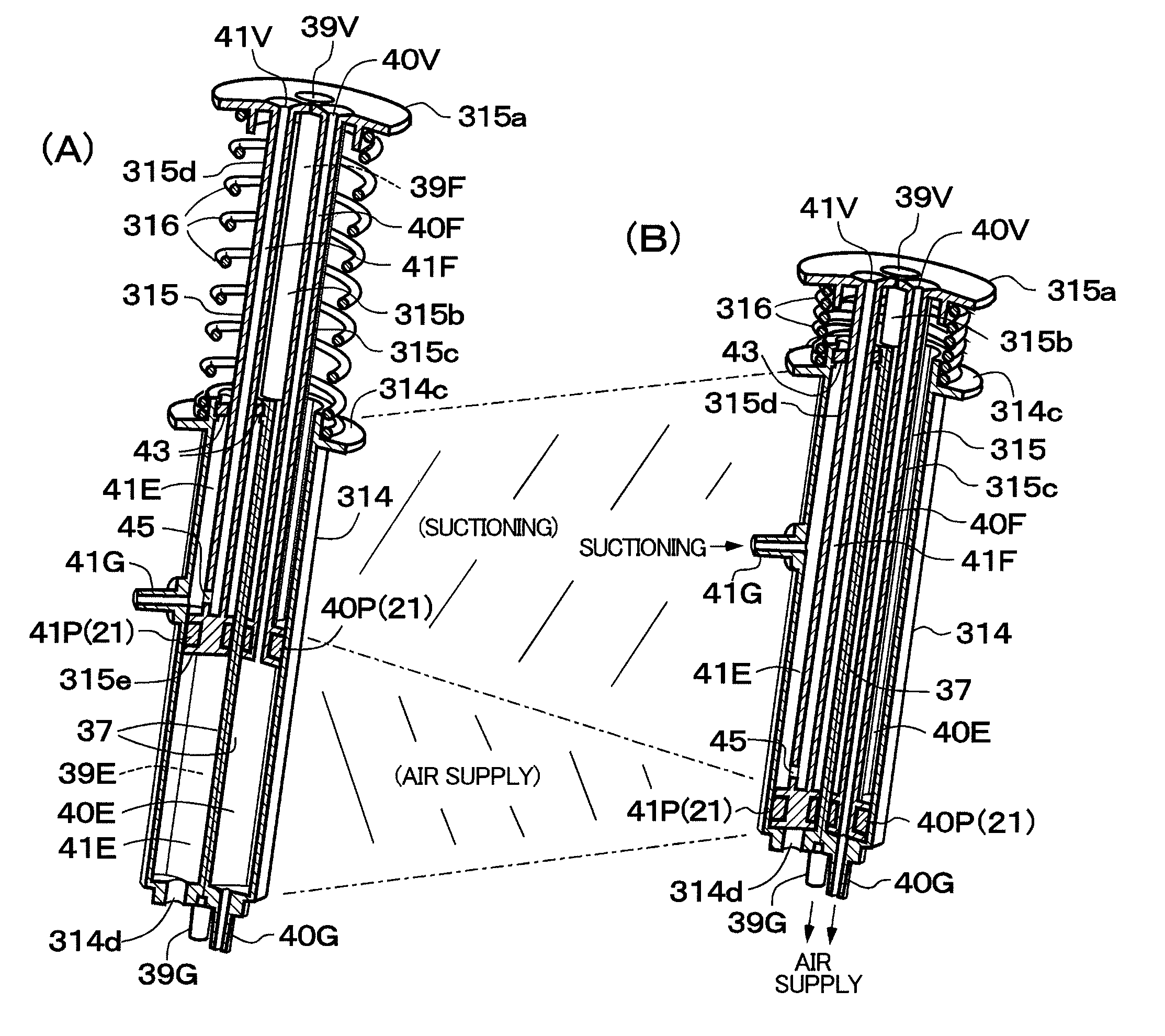
[0066]FIGS. 7 to 10 show a configuration of a third embodiment, and this third embodiment is a configuration in which two syringe space portions are arranged in series similarly to the first embodiment, in which suctioning can be also performed. As shown in FIG. 7, the syringe in the third embodiment comprises a cylindrically-shaped cylindrical body 214, a piston body 215, and a spring 216, and in the cylindrical body 214, by mounting a second cylindrical body 214b so that it is abutted against a step of an inner intermediate portion of a first cylindrical body 214a and by arranging the partition plate 17 at a distal end (stepped portion) of the second cylindrical body 214b, a first chamber 33E and a second chamber 34E as syringe space portions through which a piston portion reciprocally moves are formed in the cylindrical body 214. A first syringe port 33G is provided at a distal end of the first chamber 33E (cylindrical body 214) and a second syringe port 34G is provided on a side...


PUM


Abstract

The inside of a cylindrical body is divided into two parts, that is, a first and a second chamber, and in a piston body, a first ventilation hole and a first ventilation path of a pushing portion are formed so as to communicate with the first chamber and a second ventilation hole and a second ventilation path of the pushing portion are formed to communicate with the second chamber, and a spring for returning the piston body to its original position is provided. By pressing the pushing portion while closing the first ventilation port so as to advance the piston body, air is supplied through a syringe port on the first chamber, while by pressing the pushing portion while closing the second ventilation port, air is supplied through the syringe port on the second chamber, and by releasing the pushing operation, the piston body automatically returns to the original position.

Description

BACKGROUND OF THE INVENTION[0001]The disclosure of Japanese Patent Applications Nos. 2008-213919 and 2008-213920 filed on Aug. 22, 2008, including its specification, claims and drawings, is incorporated herein by reference in its entirety.[0002]1. Field of the Invention[0003]The present invention relates to an automatic return syringe and, more particularly to a configuration of a syringe used for air / water supply using an air / water supply tube disposed in an endoscope or the like and for suctioning through a suction tube and portable as an air / water supply device or suctioning device.[0004]2. Description of the Related Art[0005]FIG. 22 shows a configuration of a prior-art endoscope device, and an endoscope has a distal end portion 1A provided with a solid-state image pickup device, an operation portion 1B provided through a bent portion and the like, for example. In this endoscope, an air / water supply tube 3a and a water supply tube 3b and an air supply tube 3c branching from the a...

Claims


Application Information

Patent Timeline
Patent Type & Authority Patents(United States)
IPC IPC(8): A61B1/12A61M5/00A61M5/30A61M5/20
CPCA61B1/015A61M1/0058A61M1/0068A61M1/0009A61M1/0062A61M1/67A61M1/81A61M1/772A61M1/77
Inventor YAMANE, KENJI
Owner FUJIFILM CORP
Learn More