Eureka AIR delivers breakthrough ideas for toughest innovation challenges, trusted by R&D personnel around the world.

System and method for fixing a position of a steering column

Active Publication Date: 2012-12-06
STEERING SOLUTIONS IP HLDG
View PDF6 Cites 20 Cited by
  • Summary
  • Abstract
  • Description
  • Claims
  • Application Information

AI Technical Summary

Benefits of technology

[0005]In a first aspect, an adjustable steering column comprises a position lock for selectively resisting raking movement of the steering column. The position lock comprises a plurality of rake-lock discs stacked for rotation on a rake-lock control shaft and engaged to a rake-lock gear profile of a stationary rake-lock bracket. The rake-lock discs are engaged to the rak

Problems solved by technology

Such locks can be cumbersome and bulky.
They can also be susceptible to dimensional variations experienced in production, resulting in potential quality and reliability issues.

Method used


Image

  • System and method for fixing a position of a steering column
  • System and method for fixing a position of a steering column
  • System and method for fixing a position of a steering column

Examples


Embodiment Construction

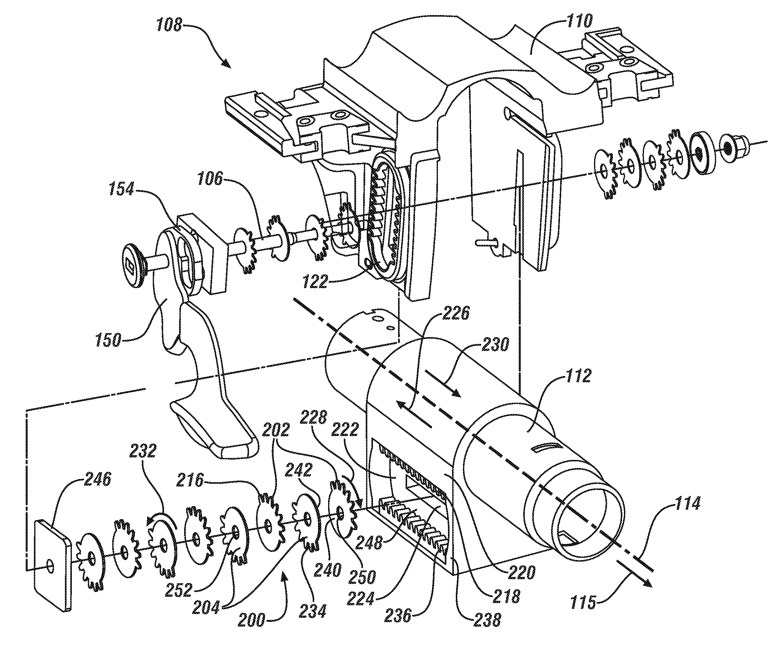
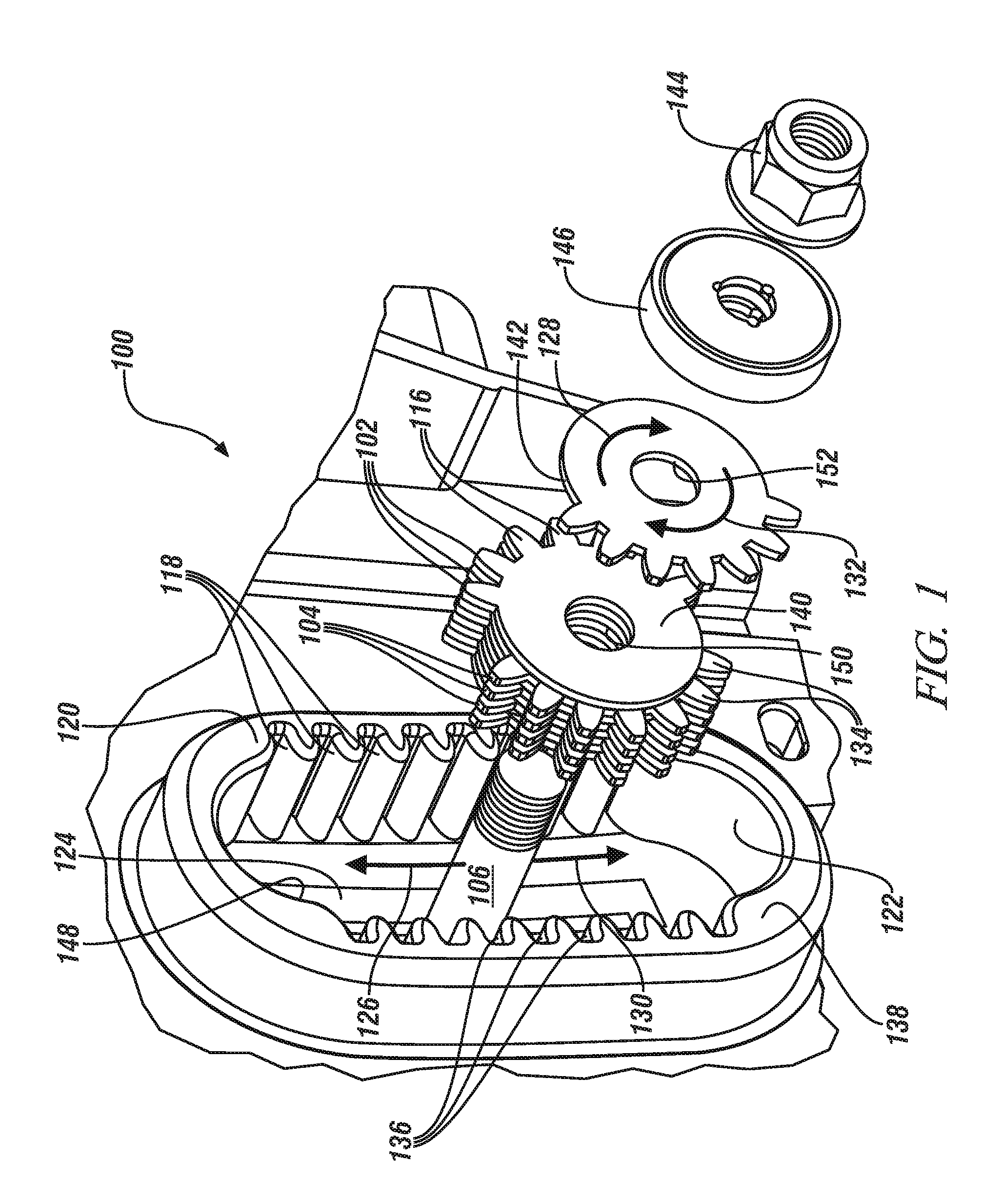
[0015]Referring now to the figures, wherein the invention will be described with reference to specific embodiments, without limiting same, FIG. 1 shows an exploded perspective view of an exemplary system 100 for fixing a rake position of a steering column. As shown in FIG. 1, one or more first rake-lock discs 102 and one or more second rake-lock discs 104 are positioned parallel to one another for free rotation about a control shaft 106. In an exemplary embodiment, each of the one or more first rake-lock discs 102 defines a circular hole 150 in approximately its center for mounting on, and facilitating free rotation about, control shaft 106. Similarly, each of the one or more second rake-lock discs 104 defines a circular hole 152 in approximately its center for mounting on, and facilitating free rotation about, control shaft 106.

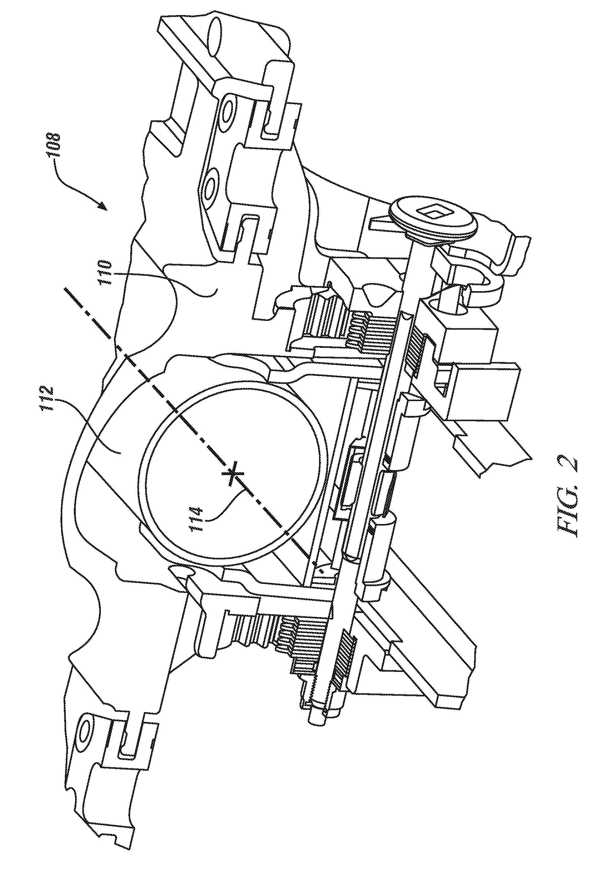
[0016]In general, as shown in FIG. 2, FIG. 5, and FIG. 6, a steering column assembly 108 comprises a stationary bracket 110, within which, and relatively to...


PUM

PropertyMeasurementUnit
Electrical resistanceaaaaaaaaaa

Abstract

A position lock for an adjustable steering column comprises a plurality of discs stacked for rotation on a control shaft and engaged to a gear profile of a stationary bracket. The discs are engaged to the gear profile so as to be caused to rotate relatively to one another as the steering column undergoes movement in the relevant direction. The discs are configured to resist rotation relative to one another when subjected to a compressive load, and the control shaft is engaged to a cam for selectively applying a compressive load to the discs. A method for selectively controlling motion of a steering column comprises coupling motion of the steering column to the relative movements of a plurality of discs, constraining the discs to rotate relative to one another as the steering column undergoes motion in the relevant direction, and selectively adjusting resistance to relative rotation the discs.

Description

CROSS-REFERENCE TO RELATED APPLICATIONS[0001]This application claims priority to U.S. Provisional Patent Application No. 61 / 493,097 filed on Jun. 3, 2011, the entire contents of which are hereby incorporated by reference herein.BACKGROUND OF THE INVENTION[0002]The present invention relates generally to locking adjustment mechanisms for steering columns and more specifically to systems and methods for fixing a position a steering column assembly while providing for adjustments in both telescoping and raking directions.[0003]Traditional steering column locks employ a friction locks arranged along the raking and telescoping ranges of motion of the steering column. Such locks can be cumbersome and bulky. They can also be susceptible to dimensional variations experienced in production, resulting in potential quality and reliability issues.[0004]Accordingly, it is desirable to have a system and method for selectively fixing and adjusting a position of a steering column with improved relia...

Claims


Application Information

Patent Timeline
IPC IPC(8): B62D1/184
CPCY10T29/49464B62D1/184
Inventor TINNIN, MELVIN L.ANSPAUGH, MICHAEL P.
Owner STEERING SOLUTIONS IP HLDG
Why Eureka
Eureka Blog
Learn More