Device for measuring a current flowing through an electric cable

Active Publication Date: 2012-12-06
MELEXIS TECH NV
View PDF10 Cites 21 Cited by
  • Summary
  • Abstract
  • Description
  • Claims
  • Application Information

AI Technical Summary

Benefits of technology

[0004]The invention is based on the object of developing a current sensor for the measurement of a current flowing through a

Problems solved by technology

It is disadvantageous in these latter current sensors that the air gap is relatively large with

Method used


Image

  • Device for measuring a current flowing through an electric cable
  • Device for measuring a current flowing through an electric cable
  • Device for measuring a current flowing through an electric cable

Examples


first embodiment

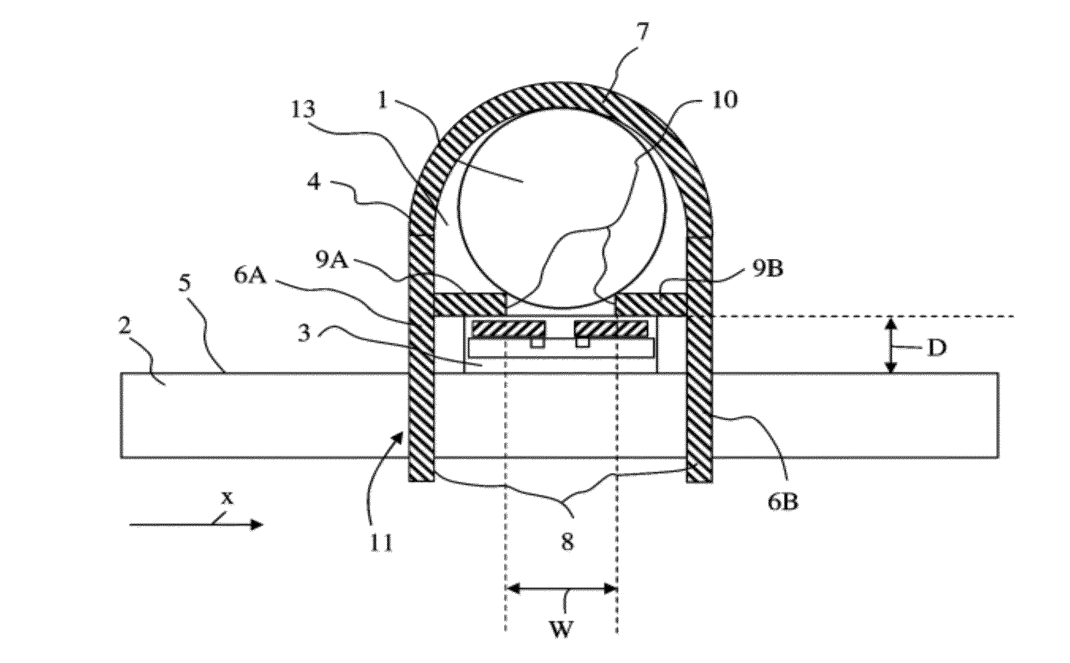
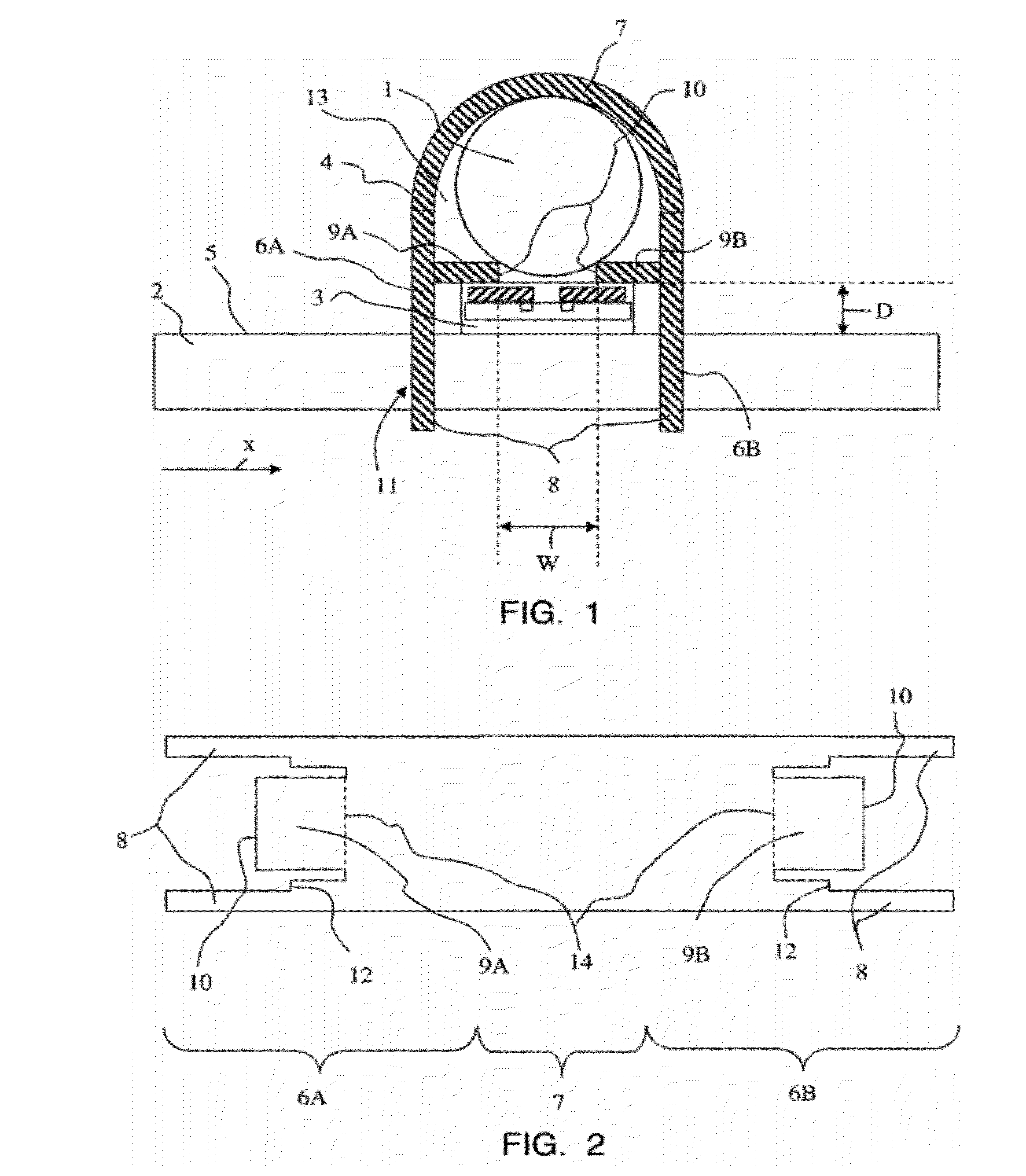
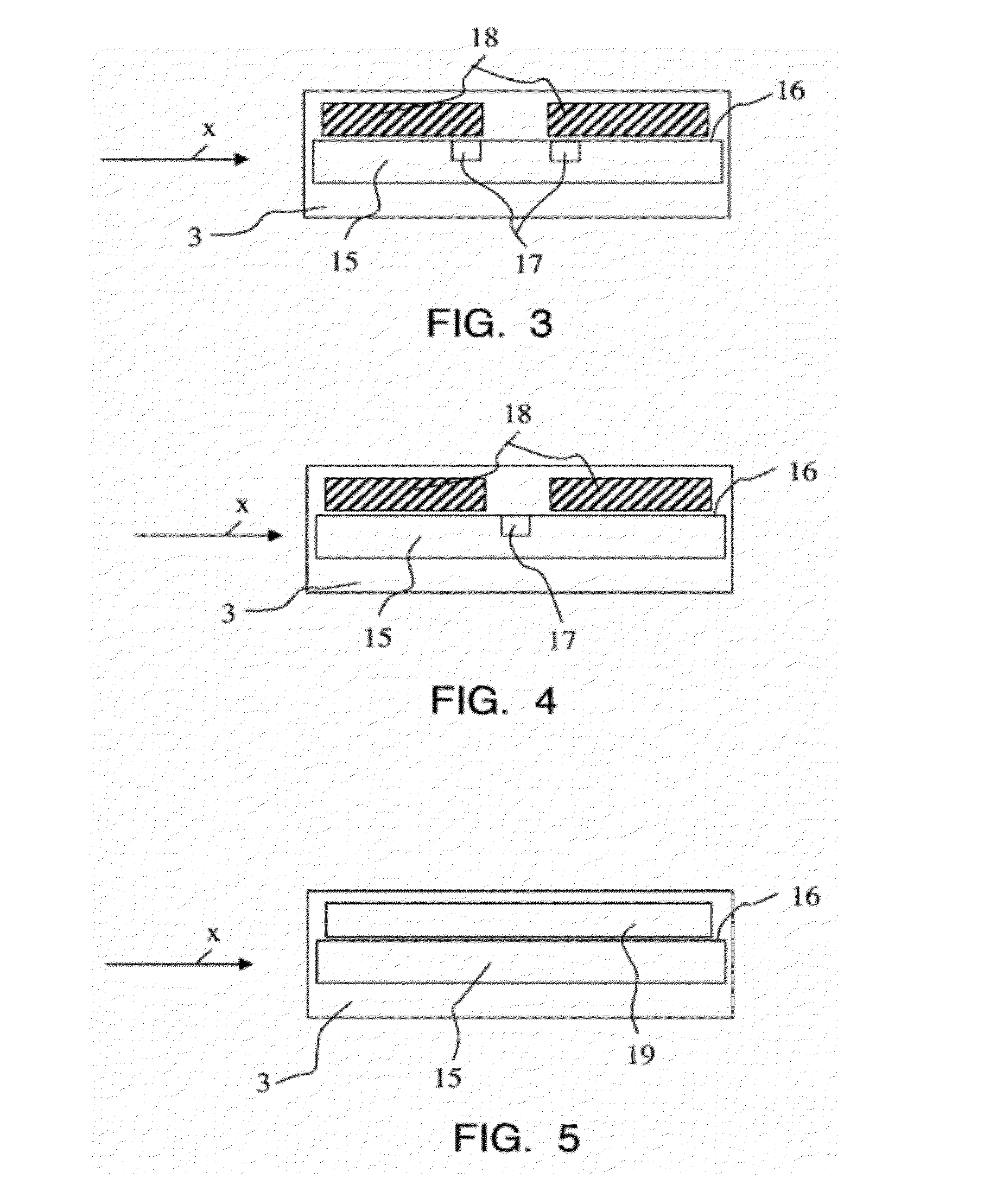
[0021]FIG. 1 shows a sectional view of a device in accordance with the invention for measuring a current flowing through an electric cable 1. The cross section of such a cable 1 is typically circular. The device comprises a printed circuit board 2, a magnetic field sensor 3 and a ferromagnetic component 4. The configuration of the magnetic field sensor 3 as shown in this drawing will be explained below in closer detail by reference to FIG. 3. The magnetic field sensor 3 is arranged on a surface 5 of the printed circuit board 2 and is sensitive to a component of the magnetic field which extends parallel to the surface 5 of the printed circuit board 2. The direction of this component is designated in the drawing as X-direction. The ferromagnetic component 4 is made from a piece of sheet metal (also see FIG. 2) which is bent in a U-shaped manner. The term of “sheet metal” shall be understood at all times in such a way that it also comprises a laminate of stacked thin sheets. The compon...

second embodiment

[0033]FIG. 15 shows a sectional view of a device in accordance with the invention for measuring the current flowing through an electric cable 1. In this embodiment, the ferromagnetic component 4 is made of a substantially annular piece of sheet metal which has two mutually opposite ends separated by an air gap, i.e. the ring is not closed. These ends are built as tongues 9A and 9B, with their front faces 10 being opposite of one another and separated by the air gap. The sheet is arranged with feet 8 which are bent off by approximately 90° in relation to the plane opened up by the ring. At least some of the feet 8 are arranged directly close to the tongues 9A and 9B, so that—after the mounting of the ferromagnetic component 4 on the printed circuit board 2—the position of the tongues 9A and 9B with respect to the printed circuit board 2 or the magnetic field sensor 3 is well-defined on the one hand and stable over a long period of time on the other hand. The inside diameter of the op...


PUM


Abstract

A device for measuring a current flowing through an electric cable comprises a printed circuit board, a magnetic field sensor and a ferromagnetic component. The ferromagnetic component comprises two tongues whose front faces are disposed opposite of each other and are separated by an air gap and further comprises at least two feet, with the tongues and/or the feet being bent off. The cable is guidable through an opening which is enclosed by the ferromagnetic component. The ferromagnetic component and the magnetic field sensor are mounted on a surface of the printed circuit board. The magnetic field sensor is sensitive to a magnetic field extending parallel to the surface of the printed circuit board. The tongues of the ferromagnetic component extend parallel to the surface of the printed circuit board (2).

Description

PRIORITY CLAIM[0001]Applicant hereby claims foreign priority under 35 U.S.C§119 from Swiss Application No. 918 / 11 filed May 30, 2011 and Swiss patent application no. 1394 / 11 filed Aug. 26, 2011, the disclosures of which are herein incorporated by reference.FIELD OF THE INVENTION[0002]The invention relates to a device for measuring a current flowing through an electric cable, i.e. a current sensor, with a magnetic field sensor measuring the strength of the magnetic field generated by the current.BACKGROUND OF THE INVENTION[0003]A large number of current sensors and devices for measuring current are known from the state of the art. U.S. Pat. No. 7,545,136 discloses a device for current measurement which is suitable for the measurement of currents up to typically 100 A that can be loaded temporarily with an overload current of up to 1000 A and is shielded against external magnetic interference fields. CH 696859 and JP 62098267 disclose current sensors in which a first Hall sensor is ar...

Claims


Application Information

Patent Timeline
IPC IPC(8): G01R33/06G01R33/02
CPCG01R15/20
Inventor RACZ, ROBERTKRUMMENACHER, PETER
Owner MELEXIS TECH NV
Why Eureka
Try Eureka