
Method and system for indicating the depth of a 3D cursor in a volume-rendered image

Inactive Publication Date: 2012-12-06
GENERAL ELECTRIC CO
View PDF25 Cites 28 Cited by
  • Summary
  • Abstract
  • Description
  • Claims
  • Application Information

AI Technical Summary

Benefits of technology

[0005]The above-mentioned shortcomings, disadvantages and problems are addressed herein which will be understood by reading and understanding the following specification.

Problems solved by technology

It is generally easy for the user to interpret the placement of the 3D cursor in directions parallel to the view plane, but it is typically difficult or impossible for the user to interpret the placement of the 3D cursor in the depth direction (i.e. the z-direction or perpendicular to the view plane).
The difficulty in determining the depth of the 3D cursor in the volume-rendered image makes it difficult to perform any tasks that require the accurate placement of the 3D cursor, such as placing markers, placing an annotation, or performing measurements within the volume-rendered image.

Method used


Image

  • Method and system for indicating the depth of a 3D cursor in a volume-rendered image
  • Method and system for indicating the depth of a 3D cursor in a volume-rendered image
  • Method and system for indicating the depth of a 3D cursor in a volume-rendered image

Examples


Embodiment Construction

[0014]In the following detailed description, reference is made to the accompanying drawings that form a part hereof, and in which is shown by way of illustration specific embodiments that may be practiced. These embodiments are described in sufficient detail to enable those skilled in the art to practice the embodiments, and it is to be understood that other embodiments may be utilized and that logical, mechanical, electrical and other changes may be made without departing from the scope of the embodiments. The following detailed description is, therefore, not to be taken as limiting the scope of the invention.

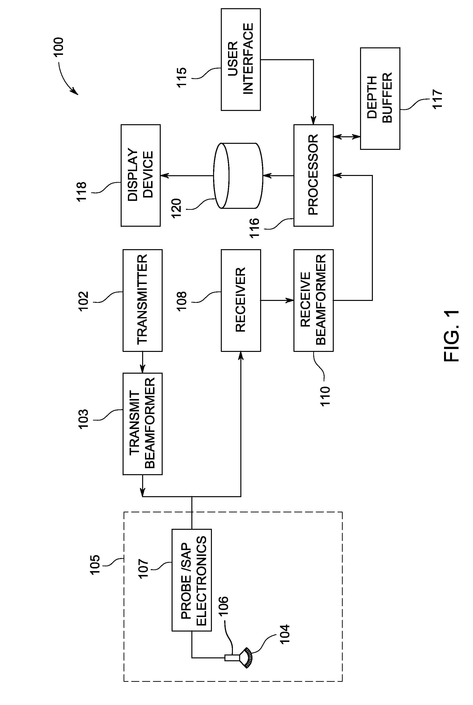
[0015]FIG. 1 is a schematic diagram of an ultrasound imaging system 100 in accordance with an embodiment. The ultrasound imaging system 100 includes a transmitter 102 that transmits a signal to a transmit beamformer 103 which in turn drives transducer elements 104 within a transducer array 106 to emit pulsed ultrasonic signals into a structure, such as a patient (not shown). A...


PUM


Abstract

A method and system include displaying a volume-rendered image and displaying a 3D cursor in the volume-rendered image. The method and system include controlling a depth of the 3D cursor with respect to a view plane with a user interface and automatically adjusting a color of the 3D cursor based on the depth of the 3D cursor with respect to the view plane.

Description

FIELD OF THE INVENTION[0001]This disclosure relates generally to a method and system for adjusting the color of a 3D cursor in a volume-rendered image in order to show the depth of the 3D cursor.BACKGROUND OF THE INVENTION[0002]Volume-rendered images are very useful for illustrating 3D datasets, particularly in the field of medical imaging. Volume-rendered images are typically 2D representations of a 3D dataset. There are currently many different techniques for generating a volume-rendered image, but a commonly used technique involves using an algorithm to extract surfaces from a 3D dataset based on voxel values. Then, a representation of the surfaces is displayed on a display device. Oftentimes, the volume-rendered image will use multiple transparency levels and colors in order to show multiple surfaces at the same time, even through the surfaces may be completely or partially overlapping. In this manner, a volume-rendered image can be used to convey much more information than an i...

Claims


Application Information

Patent Timeline
IPC IPC(8): G06T15/00
CPCG06F3/04815G06T19/00G06F3/04812G06T2219/2012G06T19/20
Inventor STEEN, ERIK N.
Owner GENERAL ELECTRIC CO
Learn More