Ubiquitously Mountable Image Display System

a display system and mountable technology, applied in the direction of electrical equipment casings/cabinets/drawers, instruments, computing, etc., can solve the problems of lack of flat mounting surface, inconvenient mounting of large screen displays, and limited use of traditional large screen displays

Active Publication Date: 2013-03-28
NANOLUMENS ACQUISITION
View PDF4 Cites 16 Cited by
  • Summary
  • Abstract
  • Description
  • Claims
  • Application Information

AI Technical Summary

Problems solved by technology

The use of traditional large screen displays is often restricted as a result of inhospitable mounting conditions.
One such inhospitable mounting condition that is often encountered both indoors as well as outdoors, is the lack of a flat mounting surface.
Unfortunately, many indoor as well as outdoor structures have various protrusions and curved surfaces located at certain spots that may coincidentally be the most desirable in terms of visibility to viewers.
As for the weight issue, even a flat mounting surface may turn out to be unsuitable for mounting a large screen display if the mounting surface is unable to bear the weight of a traditional large screen display.
As is known, the heaviness of the traditional large screen display is a result of not only the weight of the screen itself, but also the weight of the housing in which the screen is housed, and the weight of the mechanical and electronic components contained inside the housing.
The weight issue associated with using a traditional large screen display is further exacerbated by the weight of the mounting fixture, more so a customized mounting fixture when used for mounting the display on a non-flat surface.
The integrated packaging of these components, as well as other components that are not shown (frame, cabinet, etc), leads to a cumbersome arrangement having various limitations in terms of mounting considerations, cost, limited field of view etc.
The plasma display system also suffers from the same issues as described above with reference to the LCD display system.
Additionally, the plasma display system suffers from heat related, as well as weight related issues when compared to the LCD display system.
Such requirements add to the cost and complexity of the customized mounting fixture.
The extreme degree of curvature of circular mounting surface 220 would not only necessitate a customized mounting fixture but may also constitute a potential hazard in terms of creating protrusions in the path of passers-by.

Method used


Image

  • Ubiquitously Mountable Image Display System
  • Ubiquitously Mountable Image Display System
  • Ubiquitously Mountable Image Display System

Examples


first embodiment

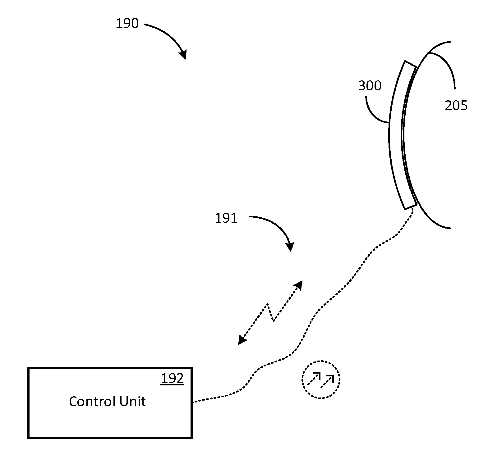
[0067]In a first embodiment, control unit 192 is a dedicated unit containing hardware and software that are expressly designed for interacting with ubiquitously mountable image display system 300.

second embodiment

[0068]In a second embodiment, control unit 192 is implemented in a general-purpose computer such as a desktop personal computer or a laptop.

[0069]Typically, control unit 192 is located at a suitable location that is remote from surface 205. Because weight considerations and mounting considerations are comparatively less important in the case of control unit 192 than in the case of ubiquitously mountable image display system 300, control unit 192 may be placed upon various suitable surfaces, such as a tabletop, a shelf, a ledge etc. This two-piece configuration (control unit 192 and ubiquitously mountable image display system 300) of display system 190 provides various advantages for ubiquitously mounting a display system in a wide variety of locations where traditional display systems may suffer from various handicaps.


PUM


Abstract

A ubiquitously mountable image display system includes a shape-reconfigurable display screen component to which is attached a plurality of circuit modules each having at least one light source. The shape-reconfigurable display screen component is formed of a material that accommodates flexing of the display screen component without creating a perceivable aberration in separation distance between two or more picture elements of an image that is rendered upon a viewing plane of the display screen component when light from the plurality of light sources is directed towards the viewing plane.

Description

DESCRIPTION OF THE RELATED ART[0001]The use of traditional large screen displays is often restricted as a result of inhospitable mounting conditions. One such inhospitable mounting condition that is often encountered both indoors as well as outdoors, is the lack of a flat mounting surface. As can be appreciated, a flat mounting surface readily accommodates various types of mounting arrangements and thereby constitutes a relatively hospitable environment for mounting traditional large screen displays.[0002]Unfortunately, many indoor as well as outdoor structures have various protrusions and curved surfaces located at certain spots that may coincidentally be the most desirable in terms of visibility to viewers. The traditional approach to solving this problem is to either mount the large screen display at a less than desirable alternative location, or to mount it upon the non-flat surface by using a customized mounting fixture along with its attendant handicaps such as material cost, ...

Claims


Application Information

Patent Timeline
Patent Type & Authority Applications(United States)
IPC IPC(8): G09G3/36G09G3/20H05K7/00
CPCG09G3/3406G02F1/133603G02F1/133305G09G2354/00G09G2380/02G06F1/16G09G3/2003G09G3/3413G09G3/3426G09G3/36
Inventor COPE, RICHARDSILZARS, ARIS
Owner NANOLUMENS ACQUISITION
Why Eureka
Try Eureka