
Magnetic Toy Block

Inactive Publication Date: 2012-12-06
HOP LEE CHEONG INDAL
View PDF20 Cites 36 Cited by
  • Summary
  • Abstract
  • Description
  • Claims
  • Application Information

AI Technical Summary

Benefits of technology

[0001]The present invention relates to toy blocks which can be attached to one and other by children to build structures. The invention more particularly, although not exclusively, relates to such toy blocks having magnetic attachment means.

Problems solved by technology

Children might be frustrated by this requirement to align the blocks correctly.

Method used


Image

  • Magnetic Toy Block
  • Magnetic Toy Block

Examples


Embodiment Construction

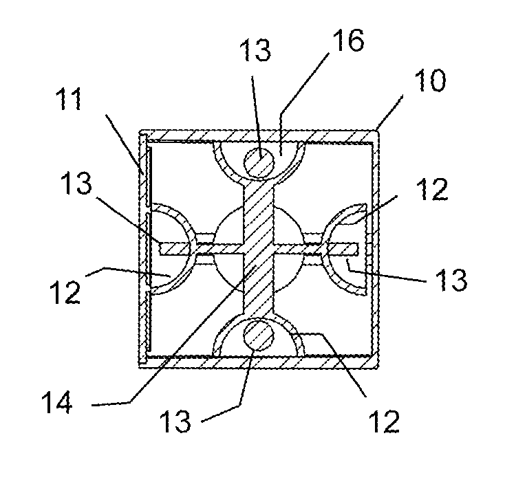
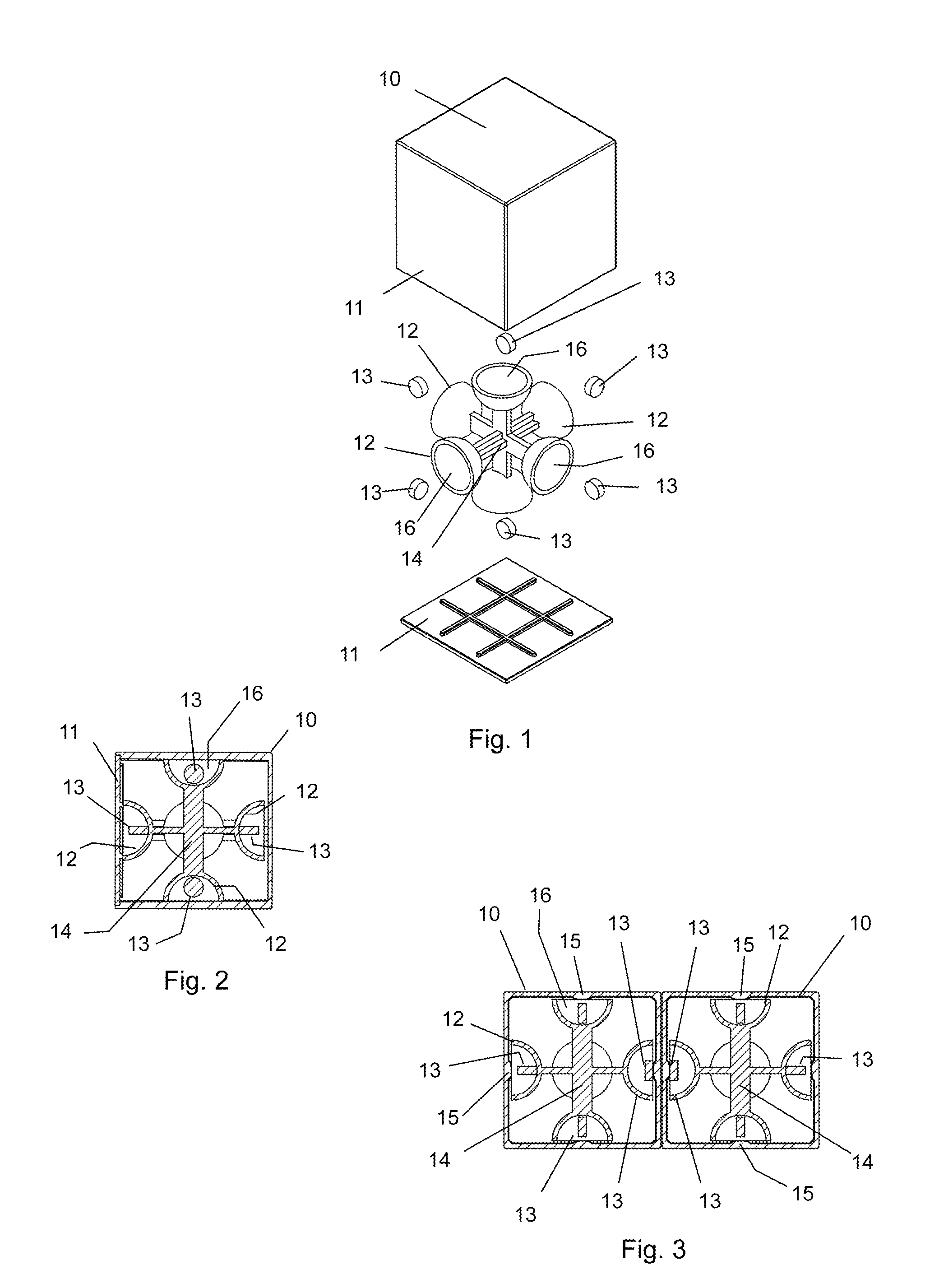
[0016]In the accompanying drawings there is depicted schematically a toy block 10 comprising a plastics body made up of six square walls 11 each having an external face and one of which is formed separately as an attachable panel which is depicted at the bottom of FIG. 1. This panel might be ultrasonically welded or otherwise affixed to close the cube.

[0017]On the inside face of each wall 11 is a central landing 15 to be described.

[0018]An internal frame 14 has six outwardly facing cups 12. These are either moulded integrally with the frame 14 or attached thereto. When the frame 14 is inserted into the body 10, each cup 12 abuts or comes into close proximity with the inside face of each wall 11 to define a compartment 16. There are six such compartments—one of which comprises the interface of a cup with the separately formed panel.

[0019]A small magnetic disk 13 is located within each compartment 16. The magnets 13 are dimensioned to reside within the compartments 16 so that they can...


PUM


Abstract

A toy block includes a body having external faces. A compartment is located behind each of the external faces and houses a magnet located freely within the compartment and adapted to turn upon magnetic interaction with another magnet external of the body so as to align attractively therewith. Two such toy blocks can be brought together face-to-face in any orientation and the magnet of one block will turn automatically into N-S alignment with a magnet of the other block so that the blocks attract and connect.

Description

BACKGROUND OF THE INVENTION[0001]The present invention relates to toy blocks which can be attached to one and other by children to build structures. The invention more particularly, although not exclusively, relates to such toy blocks having magnetic attachment means.[0002]Magnetically connectable toy blocks are known to be formed of plastics material into which magnets and optionally, pieces of ferrous metal are embedded. The magnet of one building block must be aligned with the metallic insert of another for attraction to occur in order that the blocks mutually connect. On the other hand, in order for a magnet of one block to be attracted to a magnet of another block, they must be aligned with correct N-S attractive polarity. N-N or S-S alignment will result in repulsion. Of course, if the metallic insert of one block is aligned with a metallic insert of another block, there will be no attraction. Children might be frustrated by this requirement to align the blocks correctly.[0003...

Claims


Application Information

Patent Timeline
IPC IPC(8): A63H33/04
CPCA63H33/046
Inventor MAK, KAI-SHUN
Owner HOP LEE CHEONG INDAL
Learn More