Permanent magnet drive apparatus and operational method

a permanent magnet drive and operation method technology, applied in the field of mechanical drives, can solve the problems of unresolved, unproven practical benefits, and no one, it seems, has approached the construction of permanent magnet drives, and achieves the effect of no power stroke forces

Inactive Publication Date: 2013-07-16
COLSON ANDREW E JR MR
View PDF82 Cites 36 Cited by
  • Summary
  • Abstract
  • Description
  • Claims
  • Application Information

AI Technical Summary

Benefits of technology

[0006]An advance in the art is provided by a magnetic drive apparatus having a novel magnet arrangement that is particularly suited for reciprocating operation. In an embodiment, the magnetic drive apparatus includes first and second magnet carriers carrying first and second permanent magnet arrangements. An intermediate magnet carrier is disposed between the first and second magnet carriers, and carries a third permanent magnet arrangement. The intermediate magnet carrier and the first and second magnet carriers are arranged for rotation relative to each other (relative rotation). During such relative rotation, the magnet arrangements produce magnetic interactions that result in power stroke forces. The power stroke forces cause the intermediate magnet carrier and the first and second magnet carriers to undergo reciprocation relative to each other (relative reciprocation) in first and second stroke directions during power zone portions of the relative rotation. The magnetic interactions impart substantially no power stroke forces during dead zone portions of the relative rotation. The dead zones encompass relative rotational positions of the magnet carriers wherein opposing magnetic poles of the first, second and third permanent magnet arrangements are mutually coaxially aligned but produce a substantially equal balance of push and pull magnetic forces. The relative rotation and the relative reciprocation between the intermediate magnet carrier and the first and second magnet carriers can be synchronized so that the dead zones occur proximate to top dead center and bottom dead center relative reciprocation positions of the magnet carriers (which is where relaxation of power stroke forces is desired), and so that the power stroke forces occur between the top dead center and bottom dead center relative reciprocation positions (which is where maximum magnetic force is desired).

Problems solved by technology

In many cases, the proposed devices reflect conceptions that have likely never been built, and which would be unlikely to produce practical benefits if they ever were constructed.
Yet no one, it seems, has approached permanent magnet drive construction from the standpoint of an engine designer having in mind basic principles of reciprocating engine operation.
As far as known, this problem has not been addressed to date and may be one reason why permanent magnet reciprocating drives have largely remained the domain of hobbyists and tinkerers.
During such relative rotation, the magnet arrangements produce magnetic interactions that result in power stroke forces.

Method used


Image

  • Permanent magnet drive apparatus and operational method
  • Permanent magnet drive apparatus and operational method
  • Permanent magnet drive apparatus and operational method

Examples


Embodiment Construction

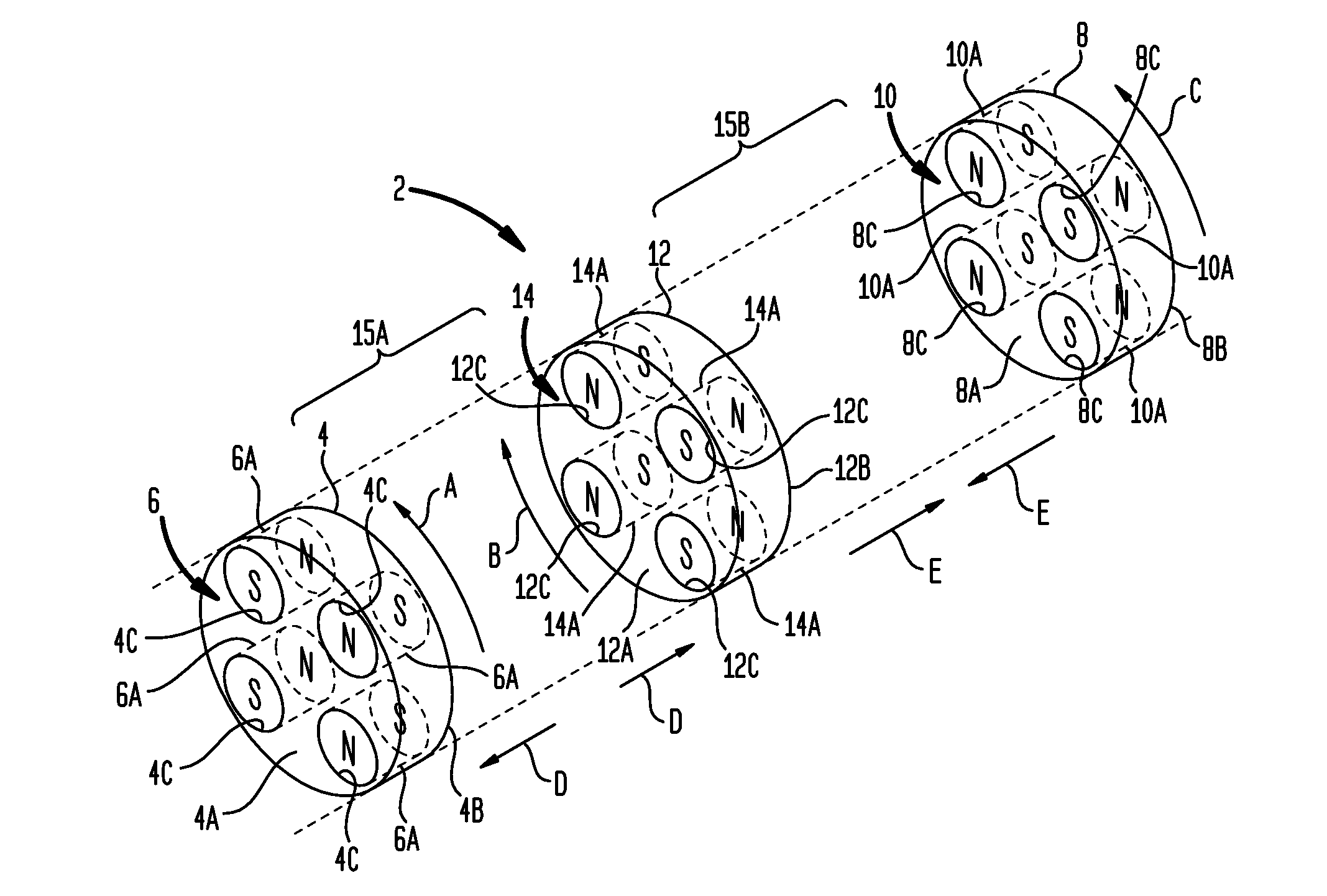
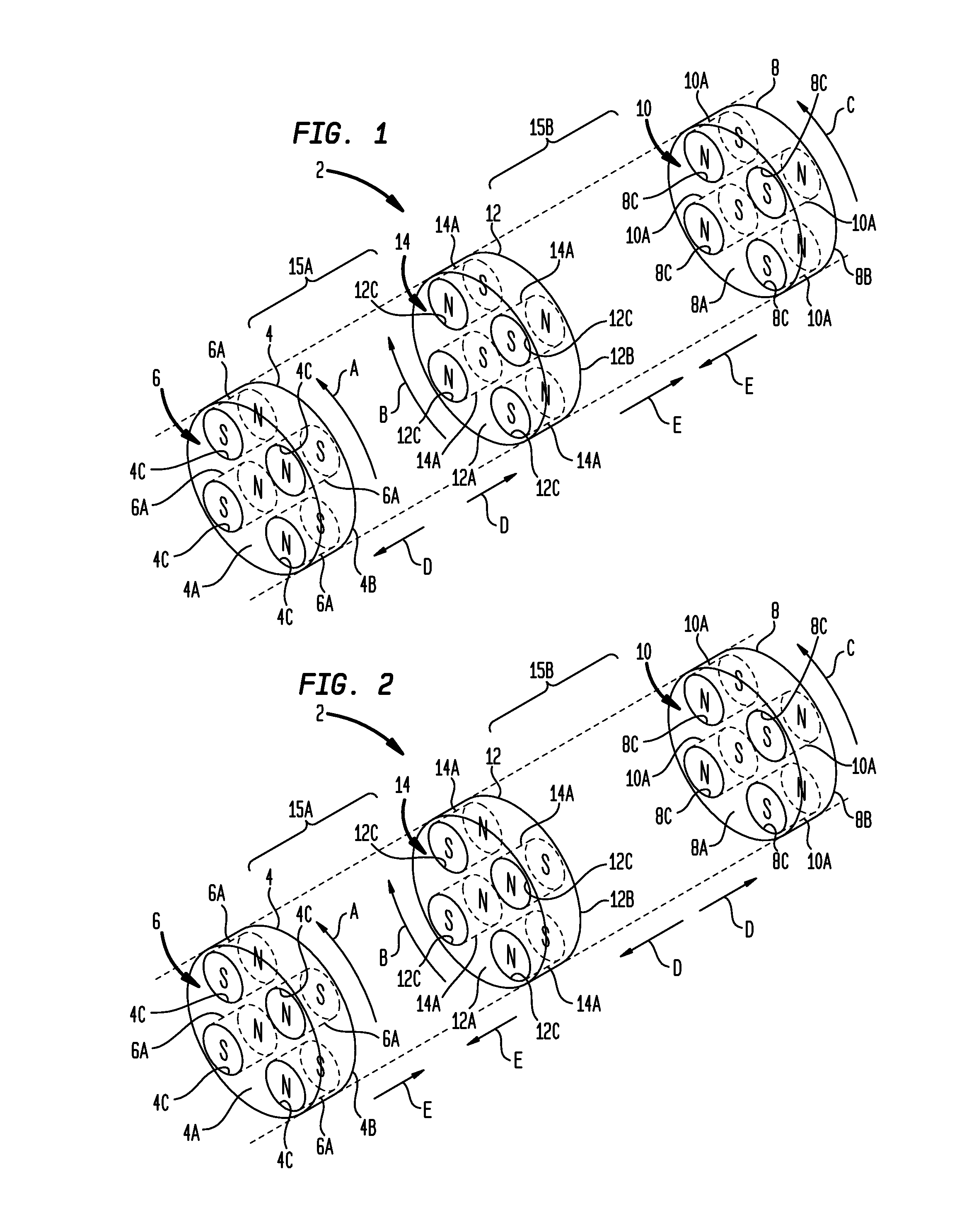
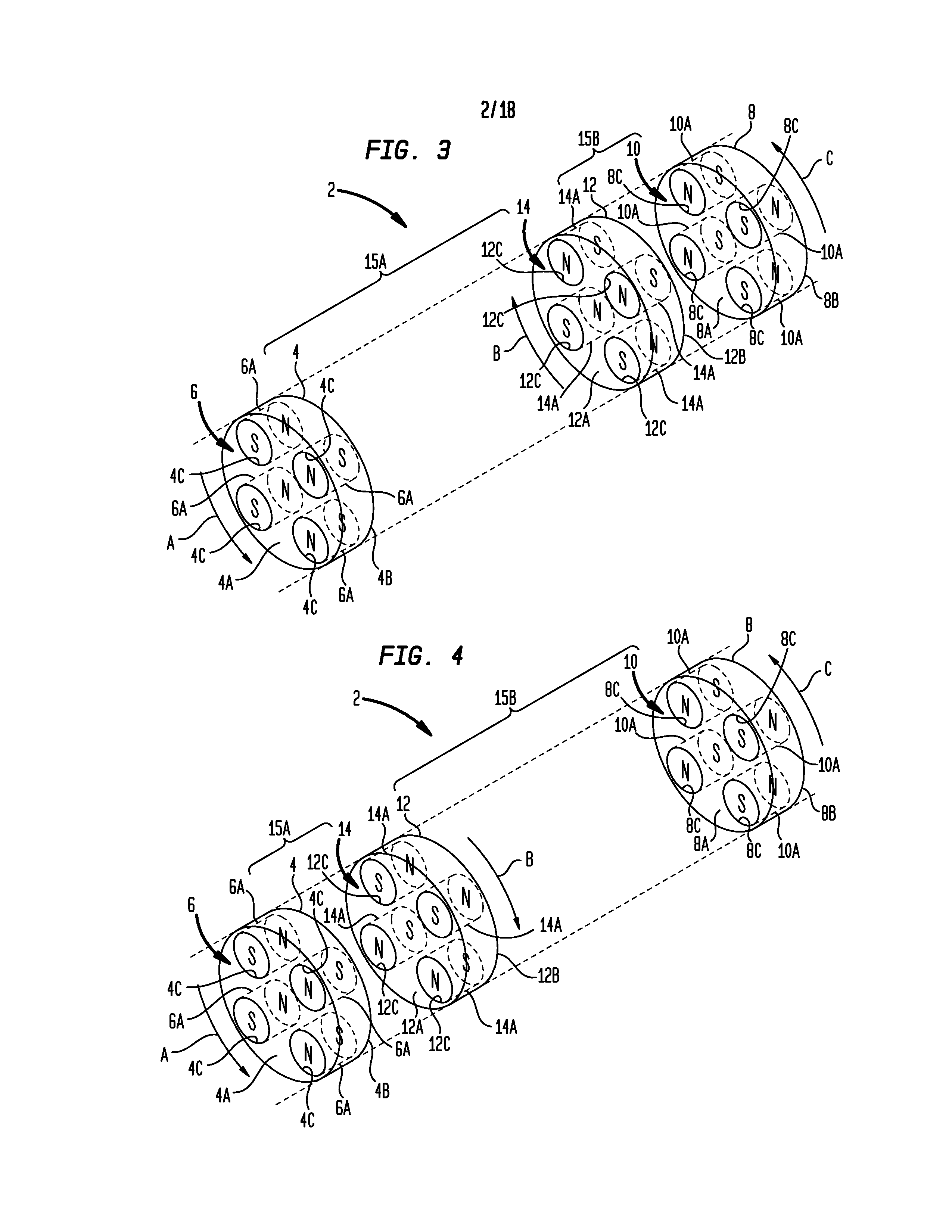
[0048]Turning now to the drawing figures, which are not necessarily to scale, like reference numerals will be used to represent like elements in all of the several views. As will be described below in connection with various alternative embodiments, a magnetic drive apparatus as disclosed herein may be used to convert a rotary input received from an input power source to a reciprocating output that may be used to drive a load. The rotary input may be continuous or intermittent, uni-directional or bi-directional. The reciprocating output may comprise a repeating cycle of reciprocal strokes. The magnetic drive apparatus uses permanent magnet arrangements that are each configured in a selected magnet pattern to create magnetic interactions as the magnet arrangements are rotated relative to each other by the input power source. These magnetic interactions deliver reciprocating power in each reciprocal stroke direction (power strokes). Advantageously, the magnetic interactions also produ...


PUM


Abstract

A magnetic drive apparatus includes first and second magnet carriers carrying first and second permanent magnet arrangements. An intermediate magnet carrier disposed between the first and second magnet carriers carries a third permanent magnet arrangement. The magnet carriers are arranged for rotation relative to each other such that the magnet arrangements produce magnetic interactions that result in power stroke forces causing the magnet carriers to undergo relative reciprocation in first and second stroke directions during power zone portions of the relative rotation. The magnetic interactions impart substantially no power stroke forces during dead zone portions of the relative rotation. The dead zones include magnet carrier relative rotation positions wherein opposing magnetic poles are mutually coaxially aligned but produce a substantially equal balance of push and pull magnetic forces. The apparatus may be synchronized so that the dead zones coincide with top dead center and bottom dead center relative reciprocation positions.

Description

BACKGROUND[0001]1. Field of the Invention[0002]The present invention relates to mechanical drives that convert input forces or torques (applied at a drive input) to output forces or torques (delivered at a drive output). More particularly, the invention concerns reciprocating drive systems that perform force or torque conversion by way of magnetic field interactions between permanent magnets.[0003]2. Description of the Prior Art[0004]By way of background, there are numerous patents, published patent applications and other literature proposing the use of permanent magnets to actuate reciprocating drive devices, such as motion converters, power transmitters, motors and other apparatus. In many cases, the proposed devices reflect conceptions that have likely never been built, and which would be unlikely to produce practical benefits if they ever were constructed. This is not to say that such disclosures are inoperative. Indeed, many permanent magnet drive systems have been constructed,...

Claims


Application Information

Patent Timeline
Patent Type & Authority Patents(United States)
IPC IPC(8): H02K41/02
CPCH02K49/102H02K7/06H02K33/00H02K2213/09H02K2201/03H02K2201/18H02K49/10
Inventor MILLER, JR., HAROLD L.COLSON, JR., ANDREW E.
Owner COLSON ANDREW E JR MR
Why Eureka
Try Eureka