Gripping device for containers

a technology for gripping devices and containers, applied in the direction of furnaces, charge manipulation, liquid handling, etc., can solve the problems of not generating uniform gripping forces and not being able to solve the problem of altering gripping forces, and achieve the effect of long service life and high performance density

Active Publication Date: 2010-08-31
KRONES AG
View PDF18 Cites 35 Cited by
  • Summary
  • Abstract
  • Description
  • Claims
  • Application Information

AI Technical Summary

Benefits of technology

[0014]In a further alternative specific embodiment, a third rotationally positioned gripper arm is likewise provided and rotationally coupled in counter-rotating direction with one of the first and second gripper arms. A permanent magnet is arranged at only one of the first and second gripper arms or its gripper arm extension; that permanent magnet comprising two bipolar permanent magnetic bodies and operating with opposing active polarities. Two additional permanent magnets respectively having the same active polarities as the allocated active polarity of the second permanent magnet are arranged in fixed fashion on both sides of the second permanent magnet. Only the second permanent magnet, which comprises the two permanent magnetic bodies, and including, perhaps, an inter-positioned separation element, moves with the one gripper arm and relative to the other, stationary permanent magnets.
[0007]As a result of combining concurrently operating, reciprocally repelling and attracting permanent magnets in such manner that with relative movements of the permanent magnets the sum of the repulsive and attractive forces is, at least in essence, constant, when the gripper arms move away from each other or towards each other, the same gripper force within the scope of the gripper range is always generated for the different gripper sizes. To the same degree that the percentage of the gripping force is decreased for example from repulsive force, there occurs an increase in the percentage of the gripping force resulting for example from attractive force. Thus, containers having different gripper sizes are held equally securely.
[0011]For support and / or moderation of the power course, a fourth permanent magnet may even be aligned relative to the respective other of the first and second permanent magnets.
[0012]In this arrangement it is useful to mount the third and preferably also the fourth permanent magnet in fixed position, while the first and second permanent magnets with their gripper arms and gripper arm extensions are in motion when the gripper arms rotate.
[0015]The first and third (or fourth) permanent magnet can also, in view of clearly defined magnetic conditions, comprise two permanent magnetic bodies and respectively requires for cooperation with the second permanent magnet only one active polarity or only one active pole.
[0013]In an alternative specific embodiment, the third permanent magnet is connected to a third pivotally positioned gripper arm or with said gripper arm's extension. The third gripper arm is useful for containers having different gripper sizes, so that the center of each captured container can be positioned in the same location, for example in relation to the swivel bearings of the gripper arms. That approach is of benefit, for example, in container filling plants so that it is possible to respectively insert the filling valve in proper fashion. In order for the third gripper arm to correctly cooperate with the first and second gripper arms, it is rotationally coupled in counter-rotating direction to one of the first and second gripper arms, so that all gripper arms can only execute pre-determined movements relative to each other.

Problems solved by technology

Even though permanent magnets ensure an exactly adjustable gripping force for a single gripper size of a container, they nevertheless have the drawback, the same as mechanical springs, of not generating uniform gripping forces when one and the same gripper is used for different gripper sizes of containers within a specified gripper range, based on a progressive or regressive characteristic line.
Until now it has not been possible to solve the problem of altering the gripping forces for one and the same gripper device to accommodate different gripper sizes.

Method used


Image

  • Gripping device for containers
  • Gripping device for containers
  • Gripping device for containers

Examples


Embodiment Construction

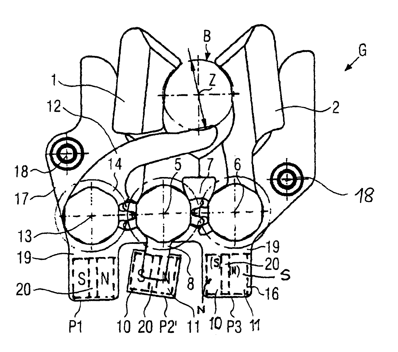
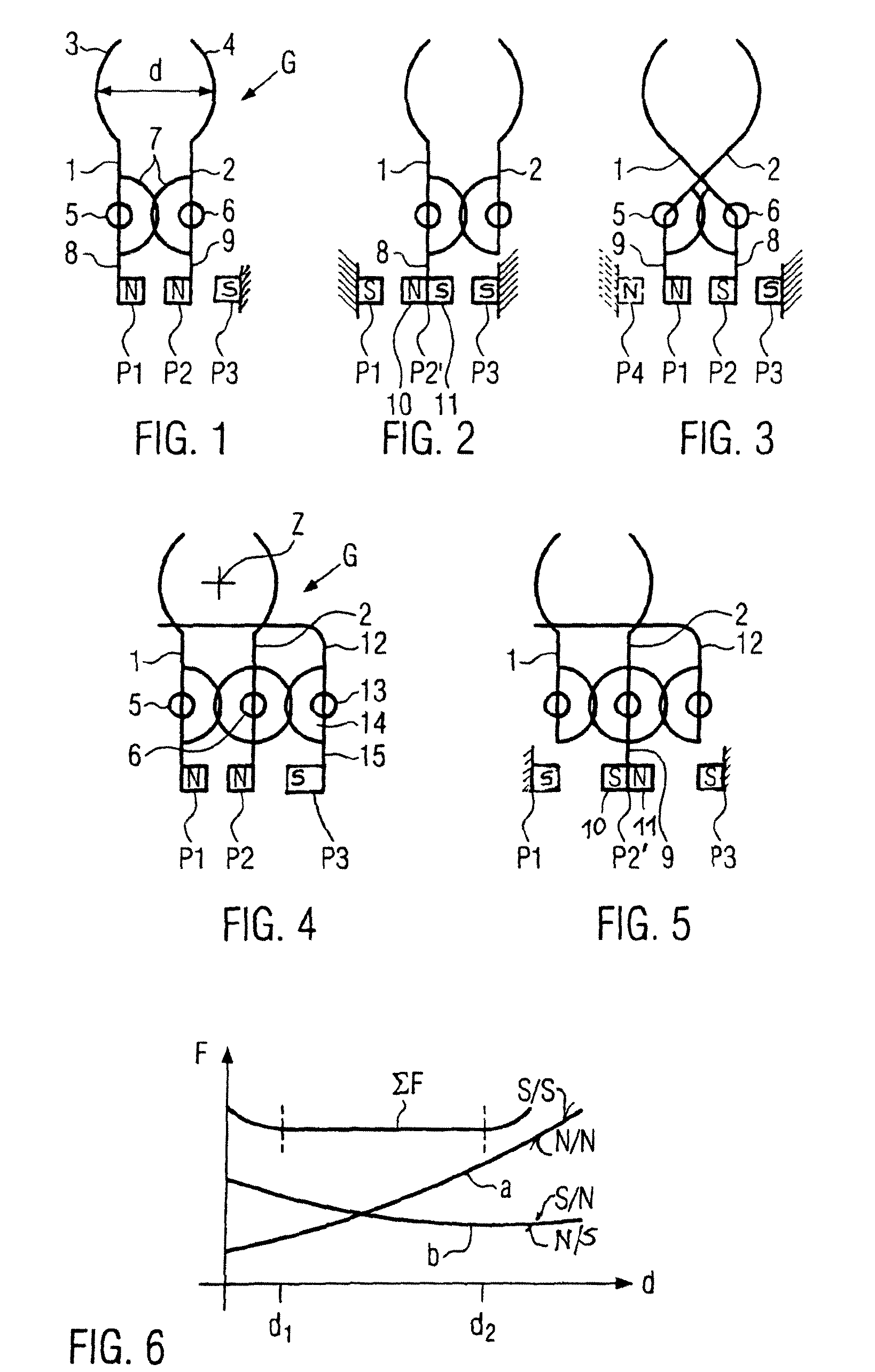
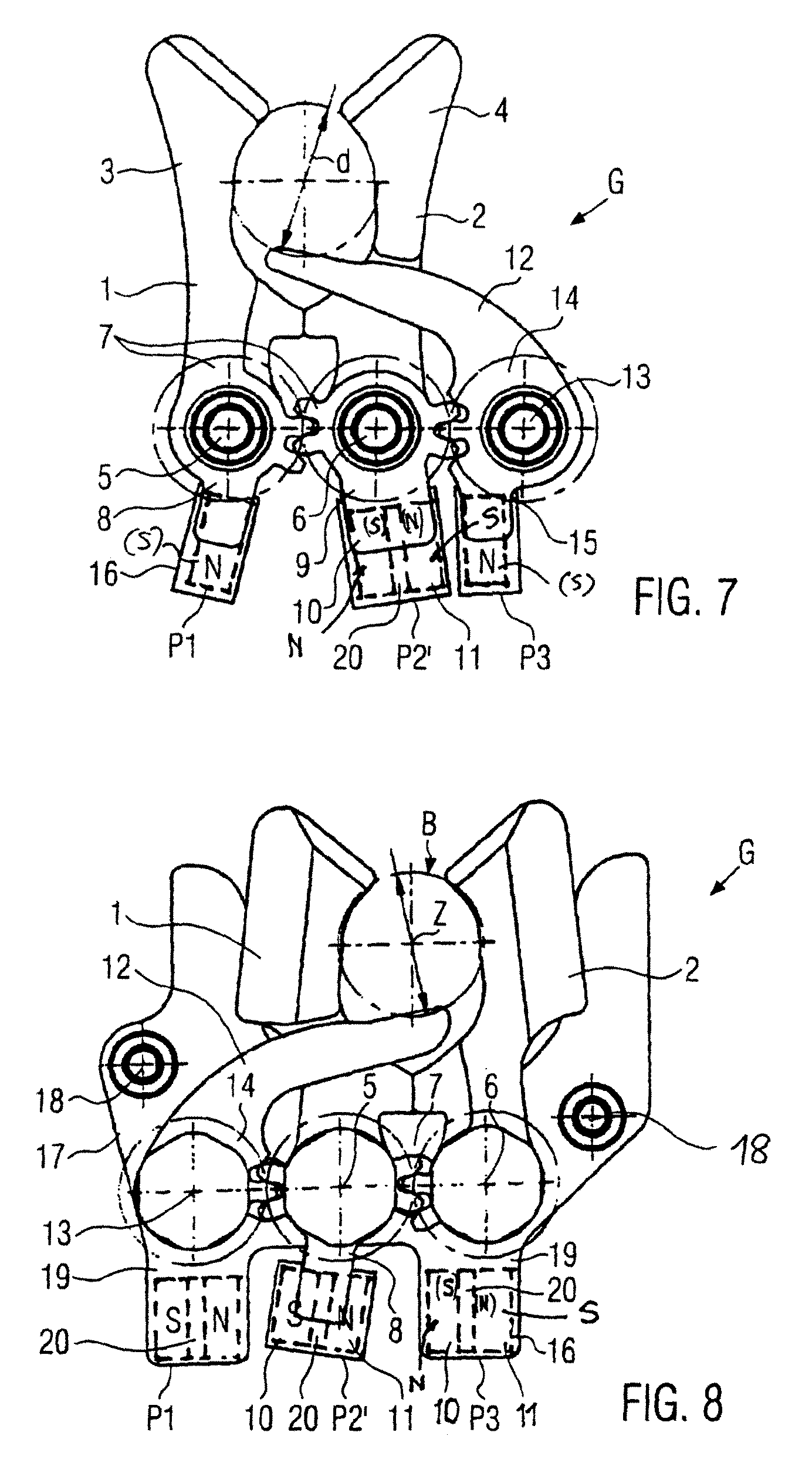
[0033]A schematic diagram is shown in FIG. 1 of a gripping device G, a so-called clamp-down gripper for container transport systems or container handling systems, in particular for bottles, and presents first and second gripper arms 1, 2 with gripper ends 3, 4 defining a gripper aperture, said gripper ends 3, 4 being pivotally positioned on remotely located swivel bearings 5, 6 and having gripper arm extensions beyond the swivel bearings. The gripper arms 1, 2 are shown, for example, in a gripper position for a gripper size d. The two gripper arms 1, 2 are rotationally coupled in the opposite direction via gear wheels or gear wheel segments 7 provided at the swivel bearings 5, 6. At the gripper arm extensions 8, 9 is respectively arranged a first permanent magnet P1 and a second permanent magnet P2. The first and second permanent magnets P1 and P2, facing each other, have the same polarities, for example N, and repel each other. A third, stationary permanent magnet P3 is aligned vis...


PUM


Abstract

A gripper for containers, in particular for bottles, with at least first and second gripper arms (1, 2) which are mounted such that they can pivot and are acted on in the gripping pivoting direction by magnetically interacting permanent magnets such as, permanent magnets which simultaneously repel one another and attract one another are arranged in such a way that the sum of the repelling and attracting forces which act in the gripping pivoting direction on the gripper arms is substantially constant within a predetermined gripping range (d1 to d2) of the gripper which covers different container gripping sizes.

Description

CROSS-REFERENCE TO RELATED APPLICATION[0001]The present application claims the benefit of priority of International Patent Application No. PCT / EP2006 / 008505, filed on Aug. 31, 2006, which application claims priority of German Patent Application No. 10 2005 041 929.1, filed Sep. 3, 2005. The entire text of the priority application is incorporated herein by reference in its entirety.FIELD OF THE DISCLOSURE[0002]The disclosure relates to a gripping device of the type used in container transport systems, such as in beverage bottling operations.BACKGROUND[0003]Such gripping devices, i.e. so called clamp-down grippers, are employed in container transport systems or container handling systems in mechanically controlled installations or in uncontrolled installations activated by the loading and unloading of containers. Mechanically controlled clamp-down gripping devices are known for example from EP 0 659 683A. Container operated clamp-down grippers are known from DE 297 13 510 U. The gripp...

Claims


Application Information

Patent Timeline
Patent Type & Authority Patents(United States)
IPC IPC(8): B65G47/34
CPCB65G47/90B67C3/242B65G2201/0247
Inventor BURGMEIER, BERTHOLD
Owner KRONES AG
Why Eureka
Try Eureka