Linear switch actuator

a technology of linear actuators and actuators, applied in the field of microwave switch actuators, can solve the problems of voice coil actuators, excessive mechanical impact on switch contacts, and association with each of these types of linear actuators, and achieve the effect of reducing magnetic permean

Inactive Publication Date: 2005-03-22
HONEYWELL LIMITED HONEYWELL LIMITÉE
View PDF18 Cites 36 Cited by
  • Summary
  • Abstract
  • Description
  • Claims
  • Application Information

AI Technical Summary

Benefits of technology

[0016](e) such that when said energizing current is applied to said coil, said armature assembly moves between said first and second stroke end positions due to the combination of the force exerted on said armature assembly due to the magnetic interaction between said energized coil and the field associated with said first and second permanent magnets and the solenoid magnetic field associated with said coil which reduces the magnetic permeance associated with said armature assembly.

Problems solved by technology

There are several weaknesses associated with each of these types of linear actuators.
This is problematic since a large force is required at the beginning of the stroke in order to overcome latching forces.
If actuators are simply made larger to overcome latching forces, the increased (i.e. very high) force at the end of the stroke results in excessively high mechanical impacts on switch contacts.
Finally, voice coil actuators having a size that is compatible with microwave switch applications do not generally provide sufficient magnetic force for practical microwave switch applications.
However, changing the armature from soft magnetic material to a permanent magnet results in a significant increase in the reluctance of the magnetic armature since μPMAGNETSOFT CORE.
For these reasons, these types of actuators are of very limited use and can be used only where an exceptionally short stroke is adequate.
The major disadvantage of a conventional voice coil actuator for microwave switch applications is that increasing the number of coil turns does not increase the magnetic force F generated.
Rather, increasing number of turns increases the gap which in turn results in a decrease of the magnetic flux that intersects the coil turns.
A voice coil actuator having a size and mass that is compatible with typical microwave switch dimensions can only generate a maximum force in the vicinity of 10 grams, which is not sufficient in practice for microwave switch applications.
However, in such a case, the reluctance of the plunger will increase significantly since μPMAGNETSOFT CORE and the magnetic flux and the magnetic force will decrease causing the actuator to be inefficient.
However, it is not desirable because the mechanical characteristics of elastic elements (e.g. springs) vary during the course of the actuator life and as such, important switch parameters, such as contact forces, latching stiffness etc. vary over time.

Method used


Image

  • Linear switch actuator
  • Linear switch actuator
  • Linear switch actuator

Examples


Embodiment Construction

energized coil and the magnetic field associated with the actuator of FIG. 4 at the middle of a stroke;

[0029]FIG. 7C is a schematic view showing the relationship between the magnetic field of the energized coil and the magnetic field associated with the actuator of FIG. 4 at the end of a stroke;

[0030]FIG. 8A is a cross-sectional view of the linear switch actuator of FIG. 4 implemented within a conventional RF SPDT switch;

[0031]FIG. 8B is a top view of a prototype model of the implementation of FIG. 8A; and

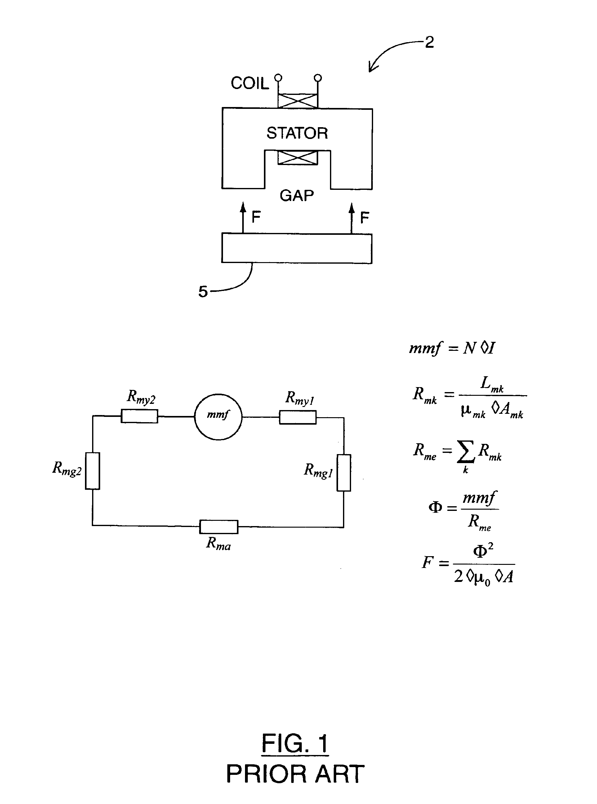
[0032]FIG. 9 is a side view of the actuator associated with a prior art conventional microwave switch for comparison purposes.

DETAILED DESCRIPTION OF THE INVENTION

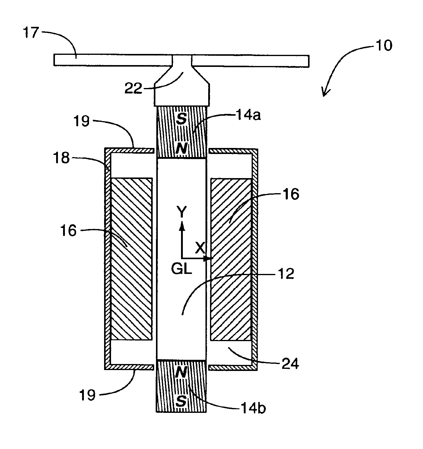
[0033]FIG. 4 illustrates a linear switch actuator 10 built in accordance with the present invention. Specifically, linear switch actuator 10 includes a mobile armature rod 12, permanent magnets 14a and 14b, an electromagnetic coil 16, a shield 18 having ferromagnetic end plates 19, and an armature piston 22. Permanent mag...


PUM

PropertyMeasurementUnit
massaaaaaaaaaa
positional displacementsaaaaaaaaaa
input impedanceaaaaaaaaaa

Abstract

A linear switch actuator for actuating a movable element within a microwave switch includes a ferromagnetic shield, a coil positioned within, and a movable armature assembly positioned within the coil. The armature assembly is coupled to the movable element and includes a ferromagnetic rod and first and second permanent magnets. The permanent magnets are coupled on either end of the rod and have opposite pole orientations. The armature assembly moves between first and second stroke end positions. When one of the permanent magnets is positioned substantially outside the shield, the magnetic permeance of the armature assembly is maximized, and the armature assembly experiences bi-stable latching between the two stroke end positions. When the coil is energized, the armature assembly moves between these positions due to magnetic interaction between the energized coil and the field associated with the permanent magnets and the solenoid magnetic field associated with the coil which reduces the magnetic permeance associated with said armature assembly.

Description

FIELD OF THE INVENTION[0002]This invention relates to microwave switch actuators and more particularly to a linear actuator for a microwave switch.BACKGROUND OF THE INVENTION[0003]Electromechanical microwave switches use electromagnetic actuators to change switch states by moving switch active elements such as RF reeds. Electro-magnetic switch actuators need to provide latching to allow the microwave switch to be powered up for only a short time period during switching. Intrinsic latching maintains the switch state during mechanical vibrations or shocks, ensures good electrical contact between the contacts, and provides extra reliability. Electromagnetic switch actuators also need to have low mass and small volume since actuators typically account for more than one half of the switch mass. The inertia forces are proportional to the mass of the mobile armature, and therefore the amount of latching force / torque necessary to maintain the switch position increases with mass, requiring a...

Claims


Application Information

Patent Timeline
Patent Type & Authority Patents(United States)
IPC IPC(8): H01H51/22
CPCH01F7/1615H01H51/2209H01H2051/2218H01F2007/1669
Inventor VLADIMIRESCU, MIHAIKWIATKOWSKI, REGINA
Owner HONEYWELL LIMITED HONEYWELL LIMITÉE
Why Eureka
Try Eureka