Coil component

a technology of components and coils, applied in the direction of transformer/inductance magnetic cores, cores/yokes, transportation and packaging, etc., can solve problems such as crosstalk, and achieve the effects of reducing crosstalk, enhancing shield effect, and improving inductance characteristics

Active Publication Date: 2008-07-31
TDK CORPARATION
View PDF3 Cites 19 Cited by
  • Summary
  • Abstract
  • Description
  • Claims
  • Application Information

AI Technical Summary

Benefits of technology

[0008]In the coil component of the present invention, the middle member with the magnetic permeability lower than that of the core and the shield member is located between the first coil part and the second coil part. This configuration reduces the crosstalk between the first coil part and the second coil part. Since the shield member is formed at least in part of the peripheral surfaces of the respective first and second coil parts, mutually different magnetic paths are formed for the first and second coil parts. Consequently, this configuration enhances the shield effect and improves the inductance characteristics. Since the shield member is resinous, it can be readily formed at any position on the first and second coil parts even in the coil component of a compact size.
[0009]Preferably, the middle member is bonded to the flange with an adhesive. When the coil component is constructed in this configuration, the middle member can define a distance between the first coil part and the second coil part in a production process. This can reduce variation in the distance between the first and second coil parts. Therefore, a minimum distance can be defined taking the crosstalk between the first and second coil parts into account whereby the coil component can be constructed in a more compact size.
[0010]Preferably, the middle member is a resinous member and is in close contact with the first and second coil parts. In this case, the middle member is filled and hardened between the first and second coil parts and in gaps to enhance the strength of the component.
[0011]Preferably, the magnetic permeability of the shield member is lower than that of the core. This allows the shield member to exercise a function equivalent to a gap, in a magnetic path composed of the core and the shield member. Therefore, it becomes feasible to achieve excellent DC bias characteristic.
[0012]The present invention reduces the crosstalk between the first and second coil parts in the coil component in which the first coil part and the second coil part are coupled together.

Problems solved by technology

In this case, a problem of occurrence of crosstalk arises when a signal is allowed to flow simultaneously through the two coil parts.

Method used


Image

  • Coil component
  • Coil component
  • Coil component

Examples


first embodiment

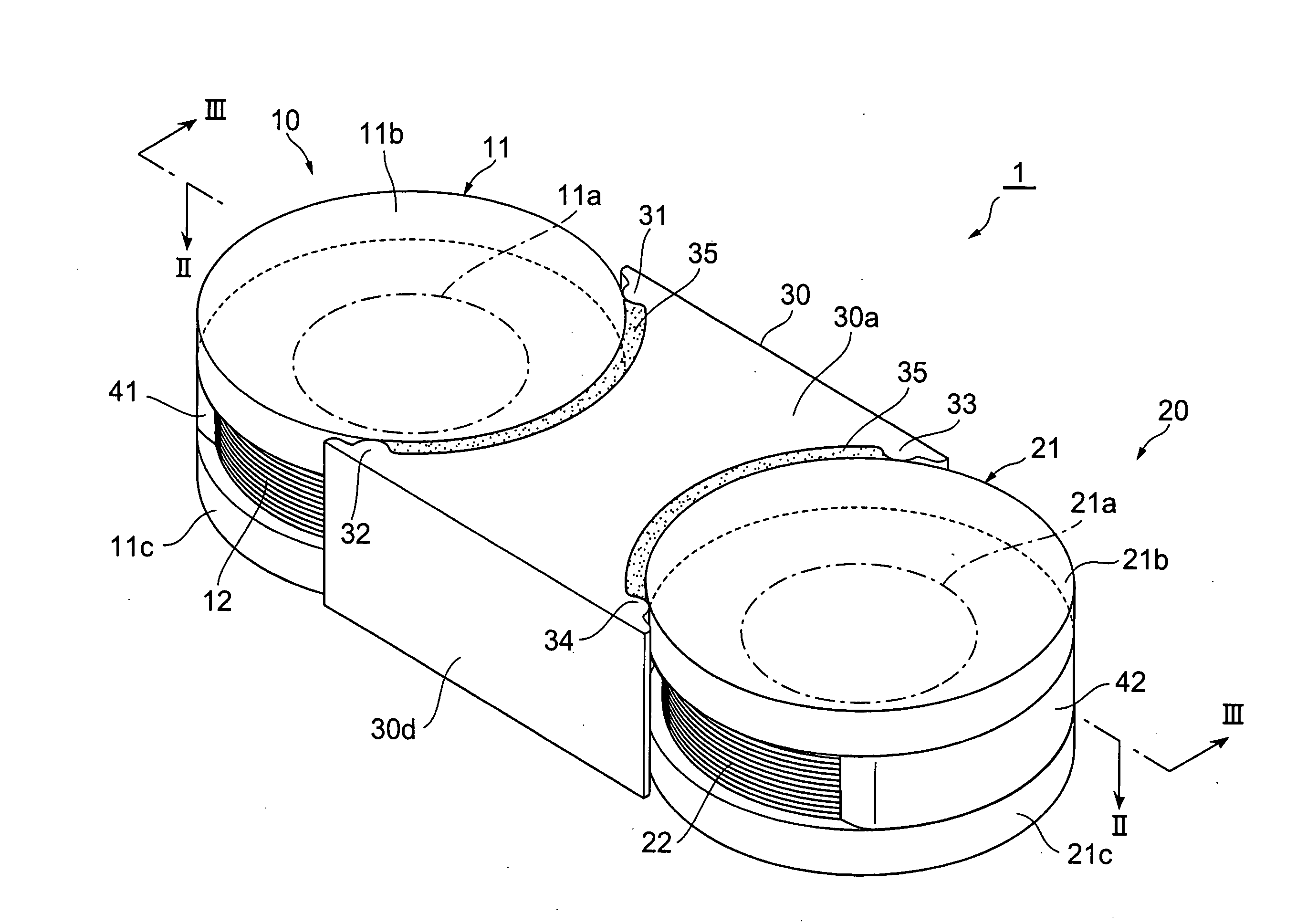
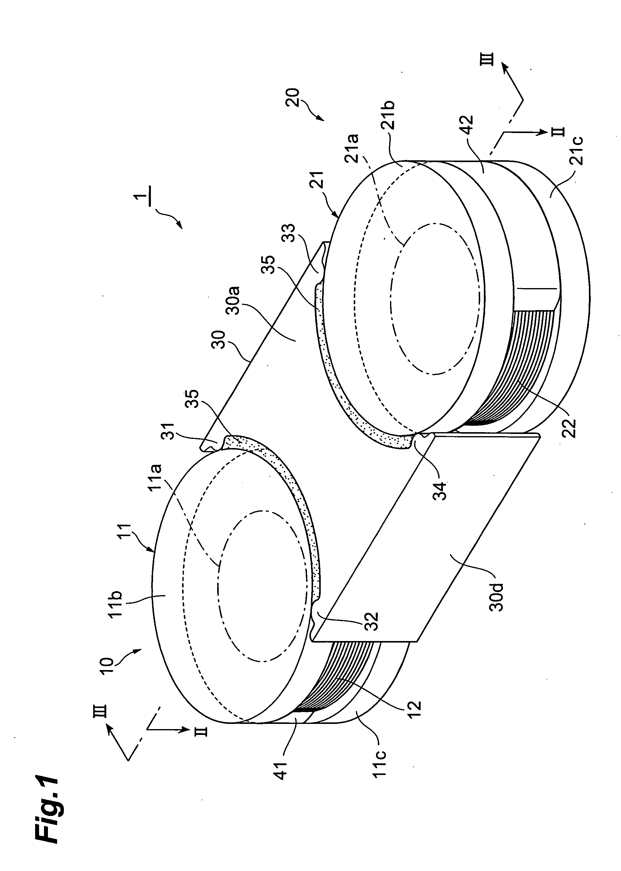
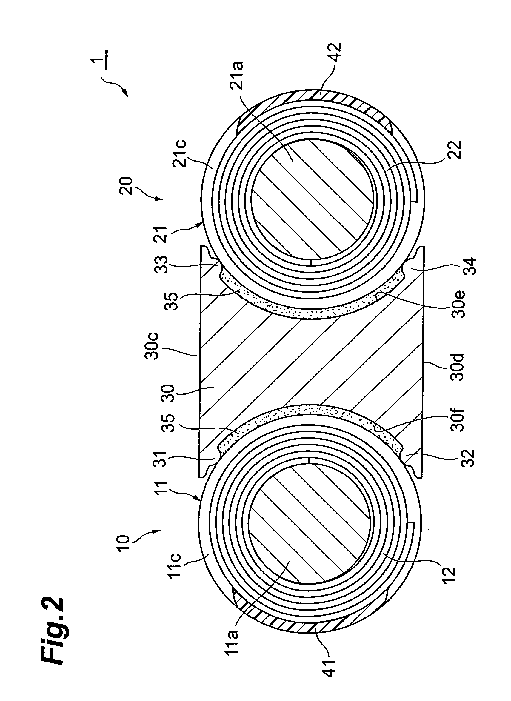
[0023]A configuration of a coil component 1 according to the first embodiment will be described with reference to FIGS. 1 to 4. FIG. 1 is a perspective view of the coil component according to the first embodiment. FIG. 2 is a schematic view showing a II-II cross section of the coil component shown in FIG. 1. FIG. 3 is a schematic view showing a III-III cross section of the coil component shown in FIG. 1. FIG. 4 is a perspective view of a middle member in the coil component shown in FIG. 1.

[0024]The coil component 1 of the present embodiment is composed of a first coil part 10 and a second coil part 20, a middle member 30, and shield members 41, 42. The middle member 30 is located between the first coil part 10 and the second coil part 20. The shield members 41, 42 are formed in the first and second coil parts 10, 20, respectively.

[0025]The first coil part 10 is composed of a core 11 and a winding 12. The core 11 is a drum core and has a winding drum 11a of a circular cylinder shape,...

first modification example of first embodiment

[0051]FIG. 5 is a sectional view of a coil component according to the first modification example of the first embodiment. The coil component 2 according to the first modification example of the first embodiment is composed of a first coil part 10, a second coil part 20, and a middle member 30 similar to those in the aforementioned coil component 1. The middle member 30 is bonded to the first coil part 10 and to the second coil part 20 with the adhesive 35 as in the coil component 1.

[0052]The shield members 43-46 in the coil component 2 will be described below. The shield members 43, 44 are formed on the outside surface of the winding 12 in the wound state on the winding drum 11a in the first coil part 10. The shield members 43, 44 are filled between the flange 11b and the flange 11c. The shield members 43, 44 are in contact with the flanges 11b, 11c. The shield member 43 is located on the plane 30c side of the middle member 30 with respect to the winding drum 11a and the shield memb...

second modification example of second embodiment

[0056]FIG. 6 is a sectional view of a coil component according to the second modification example of the first embodiment. The coil component 3 according to the second modification example of the first embodiment is composed of a first coil part 10, a second coil part 20, and a middle member 30 similar to those in the aforementioned coil component 1. The middle member 30 is bonded to the first coil part 10 and to the second coil part 20 with the adhesive 35 as in the coil component 1.

[0057]The shield members 47, 48 in the coil component will be described below. The shield member 47 is formed on the outside surface of the winding 12 in the wound state on the winding drum 11a in the first coil part 10 and is filled between the flange 11b and the flange 11c. The shield member 47 is formed throughout the entire circumference of the outside surface of the winding 12 in the wound state and is in contact with the flanges 11b, 11c throughout the entire circumference. The shield member 48 is...


PUM


Abstract

A coil component has a first coil part and a second coil part, a middle member, and a shield member. Each of the first and second coil parts includes a drum core and a winding. The middle member is located between the first and second coil parts arranged in a state in which axes of winding drums in the respective first and second coil parts are parallel to each other. The shield member is formed at least in part of an outside surface of the winding in each of the first and second coil parts and is a resin containing a magnetic material powder. The magnetic permeability of the middle member is lower than that of the core and the shield member.

Description

BACKGROUND OF THE INVENTION[0001]1. Field of the Invention[0002]The present invention relates to a coil component in which first and second coil parts are coupled together.[0003]2. Related Background Art[0004]Japanese Patent Application Laid-open No. 2006-332263 describes a coil component comprised of two coil parts and a middle core. Each of the two coil parts has a drum core with a winding wound thereon. The middle core couples the two coil parts to each other to form closed magnetic paths with their drum cores.SUMMARY OF THE INVENTION[0005]In the coil component described in the foregoing Application Laid-open No. 2006-332263, the middle core functions as a common magnetic path to the two coil parts. In this case, a problem of occurrence of crosstalk arises when a signal is allowed to flow simultaneously through the two coil parts.[0006]The present invention has been accomplished in order to solve the above problem and an object of the invention is to provide a coil component with...

Claims


Application Information

Patent Timeline
Patent Type & Authority Applications(United States)
IPC IPC(8): B65H75/02
CPCH01F3/10H01F27/34H01F17/045H01F3/14
Inventor SHOJI, ATSUSHISHINDOH, MASATOSHIKITAJIMA, YOSHIAKI
Owner TDK CORPARATION
Why Eureka
Try Eureka