
Air bubble detector

a detector and air bubble technology, applied in the field of air bubble detectors, can solve the problems of air embolism, increased risk of harm, and time spent scanning for air bubbles using less than optimal frequencies

Active Publication Date: 2012-12-13
ZEVEX
View PDF2 Cites 3 Cited by
  • Summary
  • Abstract
  • Description
  • Claims
  • Application Information

AI Technical Summary

Benefits of technology

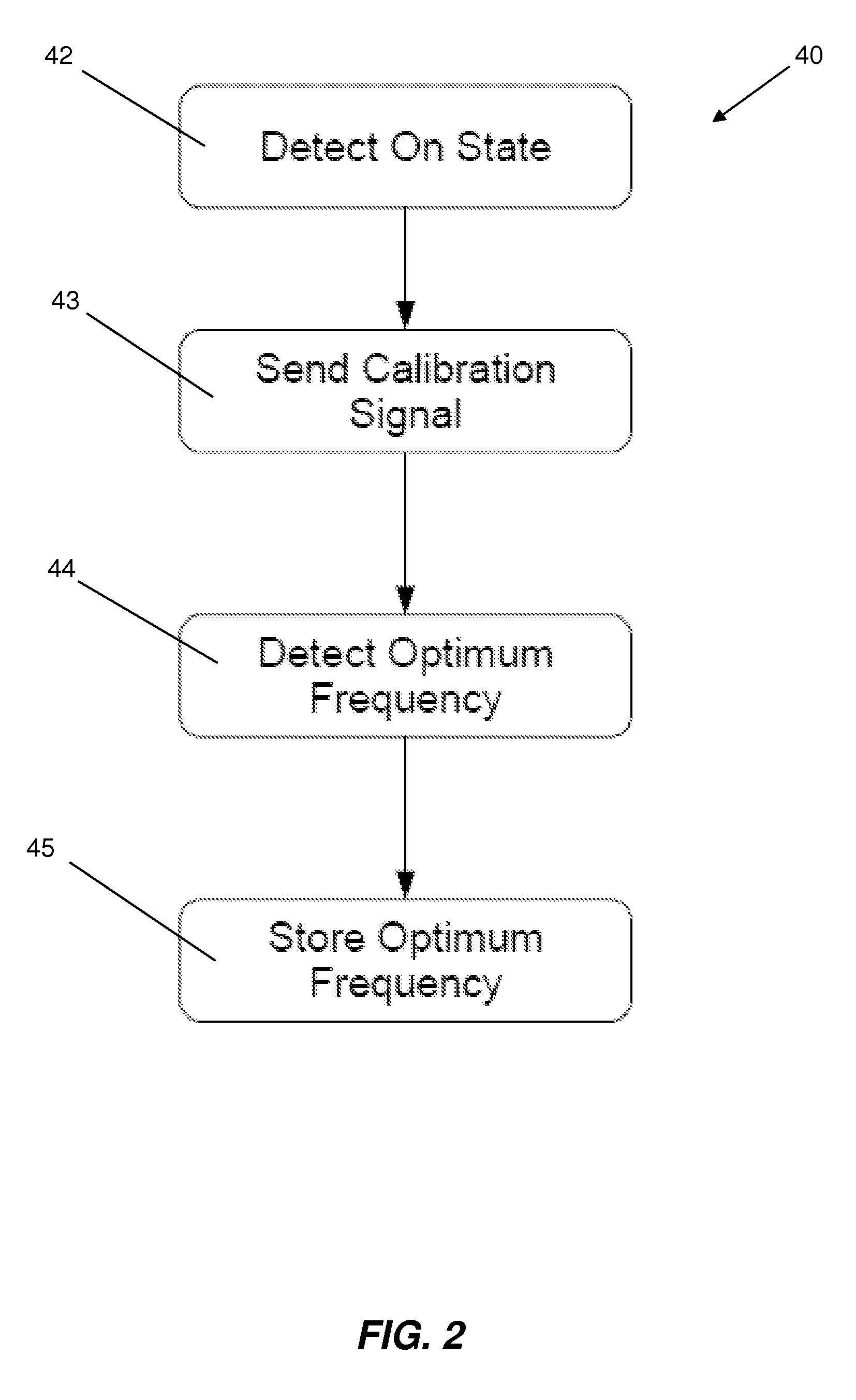
The present invention provides an improved air bubble detector that can accurately detect and characterize bubbles in a fluid or air. The detector uses a sweeping frequency range to identify an optimum frequency for better bubble detection. It also measures the amount of time a sensor signal is above a threshold to determine the air bubble that caused the signal response. Additionally, the invention provides a series of bubble detectors that can be used in combination to determine the direction and speed of bubbles in the fluid.

Problems solved by technology

For example, in medical applications, if air is introduced into the bloodstream via an infusion tube, an air embolism may occur.
In these situations, the greater the volume of air, the greater could be the risk of harm.
Sweeping the entire spectrum typically results in time spent scanning for bubbles using less than optimal frequencies.
False alarms have become a problem in bubble detection.
False alarms may decrease the trust in the system and increase the workload of staff, and may cause problems or delays in dosing of medication or the like.

Method used


Image

  • Air bubble detector
  • Air bubble detector
  • Air bubble detector

Examples


Embodiment Construction

[0022]The invention and accompanying drawings will now be discussed in reference to the numerals provided therein so as to enable one skilled in the art to practice the present invention. The drawings and descriptions are exemplary of various aspects of the invention and are not intended to narrow the scope of the appended claims.

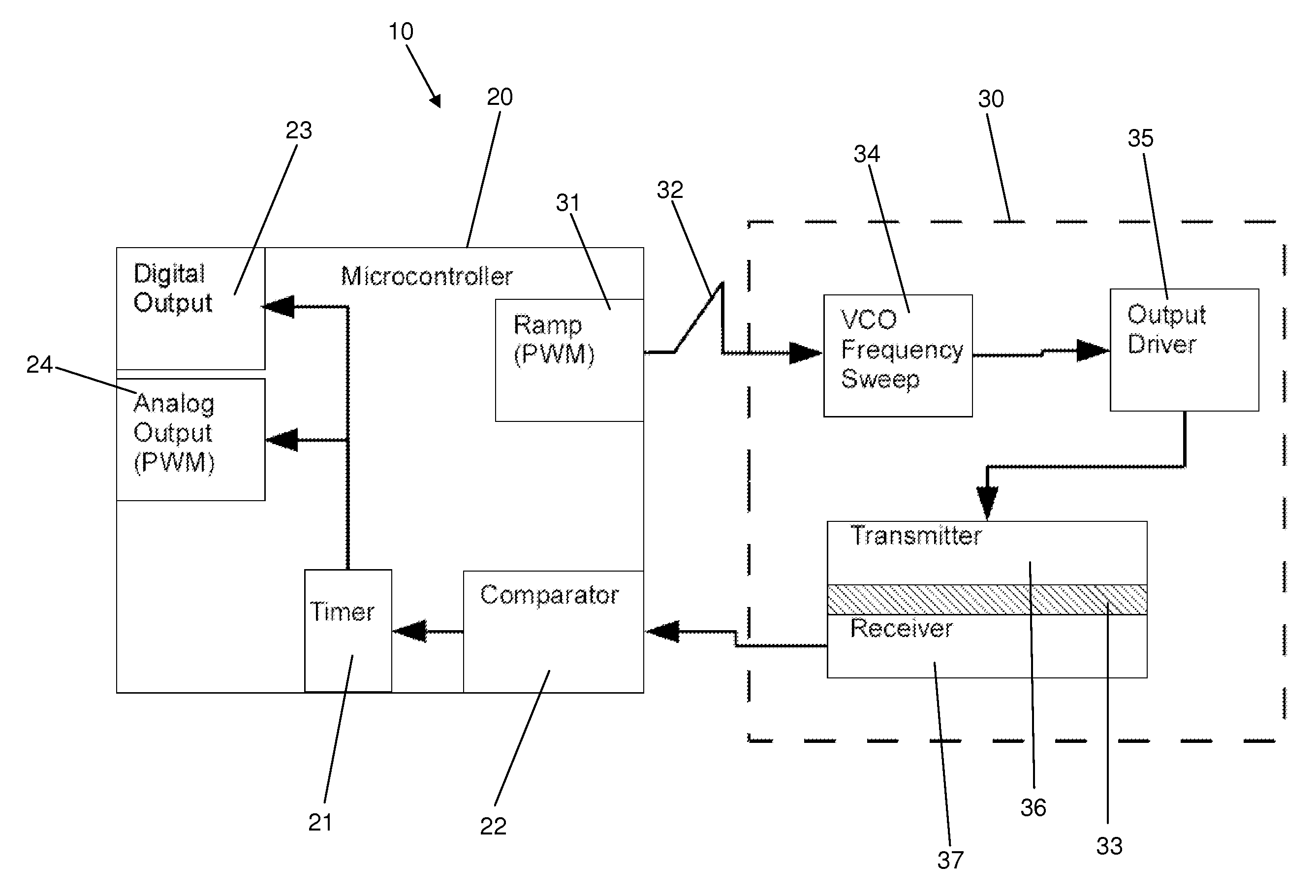
[0023]Turning now to FIG. 1, a functional diagram of an air bubble detector system 10 is shown. The detector 10 includes a microcontroller 20 and a sensor circuit 30. The microcontroller 20 determines the optimum range of scanning frequencies for the detector and operates the detector using this range of frequencies. When operating the detector 10, the controller 20 determines optimal frequencies for scanning and performs scans, recording the duration or width of a signal received which exceeds a predetermined threshold. The controller 20 may periodically scan the entire frequency to update the optimum frequency range used for scanning. The microcontroller ...


PUM

PropertyMeasurementUnit
frequencyaaaaaaaaaa
resonant frequencyaaaaaaaaaa

Abstract

Air bubbles may be characterized by an air bubble detector by choosing an optimum set of frequencies and then comparing a return signal from a sensor receiving those frequencies against an internal reference. The number of pulses that exceed the internal reference represents a width and may be counted. The width, as counted, may be correlated to bubble characteristics including volume.

Description

PRIORITY[0001]The present application claims the benefit of U.S. Provisional Application Ser. No. 61 / 150,706, filed Feb. 6, 2009 which is herein incorporated by reference in its entirety.THE FIELD OF THE INVENTION[0002]The present invention relates to air bubble detectors. More specifically, the present invention relates to an air bubble detector and related control circuitry with improved sensing and reporting of air bubbles.BACKGROUND[0003]Bubble detectors have become an important safety feature in many applications including industrial and medical applications. For example, in medical applications, if air is introduced into the bloodstream via an infusion tube, an air embolism may occur. The effects of an air embolism may range from little or no effect to death, typically depending on the amount of air which is introduced. Industrially, it is often desirable to detect the presence of air in a fluid stream to more accurately dose the fluid or to avoid introduction of air into a sy...

Claims


Application Information

Patent Timeline
Patent Type & Authority Applications(United States)
IPC IPC(8): G01N29/02
CPCG01N29/032G01N29/036G01N2291/102G01N2291/02433G01N2291/048G01N29/348
Inventor STRINGHAM, MARKMILLIS, ROGERFOLEY, JOHNBLAINE, DAVID
Owner ZEVEX
Learn More