Diaphragm infusion machine

A diaphragm and diaphragm pump technology, applied in pressure infusion, hypodermic injection equipment, flow control and other directions, can solve problems such as poor control of infusion speed, contaminated liquid medicine, shaft falling off, etc., to avoid dangerous situations, improve reliability, intelligent control effect

Inactive Publication Date: 2017-01-04
鲁绍荣
View PDF0 Cites 3 Cited by
  • Summary
  • Abstract
  • Description
  • Claims
  • Application Information

AI Technical Summary

Problems solved by technology

If the infusion is too fast or too slow, it is difficult to achieve the expected therapeutic effect, and even affect the safety of nursing care.
[0003] The traditional infusion method has poor infusion speed control. During the infusion, the infusion bottle or the infusion bag needs to be lifted high, which is inconvenient for the patient to move during the infusion, and it is also inconvenient to lift the infusion bottle or the infusion bag high in the ambulance with a small space; And th...

Method used


Image

  • Diaphragm infusion machine
  • Diaphragm infusion machine

Examples


Embodiment 1

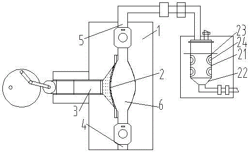
[0029] Such as figure 1Diaphragm infusion machine shown, pump body 1, diaphragm 2, piston rod 3, liquid inlet channel 4, liquid outlet channel 5, pump cavity 6, liquid storage 21, liquid collector 22, heating tank 23 and heating tube 24 , the diaphragm pump includes a pump body 1, a diaphragm 2 and a piston rod 3, the pump body 1 is provided with a pump chamber 6, the pump chamber 6 is provided with a diaphragm 2, and the pump body 1 is equipped with a pump communicating with the pump chamber 6 The piston rod 3, the pump body 1 is provided with a liquid inlet channel 4 and a liquid outlet channel 5, and the liquid inlet channel 4 and the liquid outlet channel 5 are provided with a float check valve; the pulse damper The outlet is provided with a bubble detector and a flow sensor. The bubble detector and the flow sensor are respectively connected to the MCU. The MCU is also connected to the driving motor of the diaphragm pump and the touch screen. The diaphragm pump is connecte...

Embodiment 2

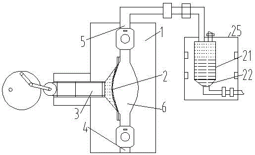
[0039] Such as figure 1 Diaphragm infusion machine shown, pump body 1, diaphragm 2, piston rod 3, liquid inlet channel 4, liquid outlet channel 5, pump chamber 6, liquid storage 21, liquid collector 22 and heating shell 25, the diaphragm The pump includes a pump body 1, a diaphragm 2 and a piston rod 3. The pump body 1 is provided with a pump chamber 6, the pump chamber 6 is provided with a diaphragm 2, and the pump body 1 is equipped with a piston rod 3 communicating with the pump chamber 6. The pump body 1 is provided with a liquid inlet channel 4 and a liquid outlet channel 5, and the liquid inlet channel 4 and the liquid outlet channel 5 are provided with a float check valve; the outlet of the pulse damper is provided with an air bubble Detector and flow sensor, air bubble detector and flow sensor are respectively connected with MCU, and described MCU is also connected with the driving motor of diaphragm pump, touch display screen, and diaphragm pump is connected with driv...


PUM


Abstract

The invention discloses a diaphragm infusion machine which comprises a diaphragm pump and a pulse damper, wherein the pulse damper is arranged at the outlet of the diaphragm pump; the diaphragm pump comprises a pump body, a diaphragm and a piston rod; a pump chamber is formed in the pump body; the diaphragm is arranged in the pump chamber; the piston rod communicated with the pump chamber is arranged in the pump body; a liquid inlet flow channel and a liquid outlet flow channel are formed in the pump body; one-way float valves are arranged in the liquid inlet flow channel and the liquid outlet flow channel; a bubble detector and a flow sensor are arranged at the outlet of the pulse damper; the bubble detector and the flow sensor are respectively with MCU; the MCU is connected with a driving motor of the diaphragm pump and a touch display screen; the diaphragm pump is connected with the driving motor; and the driving motor is a variable frequency motor. The technical aim of the invention is to provide the diaphragm infusion machine which can be automatically controlled. According to the machine, the condition that liquid medicine is contaminated by dropping debris due to friction of a sealing element is avoided, and infusion damping is avoided.

Description

technical field [0001] The invention relates to the field of medical equipment, in particular to a diaphragm transfusion machine. Background technique [0002] Intravenous infusion is a commonly used method of administration in clinical treatment, and the speed of intravenous infusion varies according to the nature of the drug and the constitution of the patient. If the infusion is too fast or too slow, it is difficult to achieve the expected therapeutic effect, and even affect the safety of nursing. [0003] The traditional infusion method has poor infusion speed control. During the infusion, the infusion bottle or the infusion bag needs to be lifted high, which is inconvenient for the patient to move during the infusion, and it is also inconvenient to lift the infusion bottle or the infusion bag high in the ambulance with a small space; And the existing infusion pump is either the price is too high or the infusion pump has a very strong pulse, the strong pulse will make t...

Claims


Application Information

Patent Timeline
IPC IPC(8): A61M5/142A61M5/44A61M5/168
CPCA61M5/14224A61M5/16804A61M5/44
Inventor 鲁绍荣
Owner 鲁绍荣
Why Eureka
Try Eureka