Power breaker

a power breaker and power supply technology, applied in the direction of high-tension/heavy-dress switch, contact vibration/shock damping, metal casing arrangement, etc., can solve the problem of giving rise to contact chattering, etc., to achieve simple, compact and inexpensive configuration, the effect of suppressing contact chattering

Active Publication Date: 2012-12-13
MITSUBISHI ELECTRIC CORP
View PDF4 Cites 9 Cited by
  • Summary
  • Abstract
  • Description
  • Claims
  • Application Information

AI Technical Summary

Benefits of technology

[0010]According to the invention, the fine motion mechanism portion has the chattering suppression portion formed by stacking up plural ring members having corresponding slope shapes or curved surface shapes in stacked portions. Kinetic energy generated upon collision can be absorbed by trapping

Problems solved by technology

The butt structure, however, may possibly give rise to chattering of the contacts when t

Method used


Image

  • Power breaker
  • Power breaker
  • Power breaker

Examples


embodiments

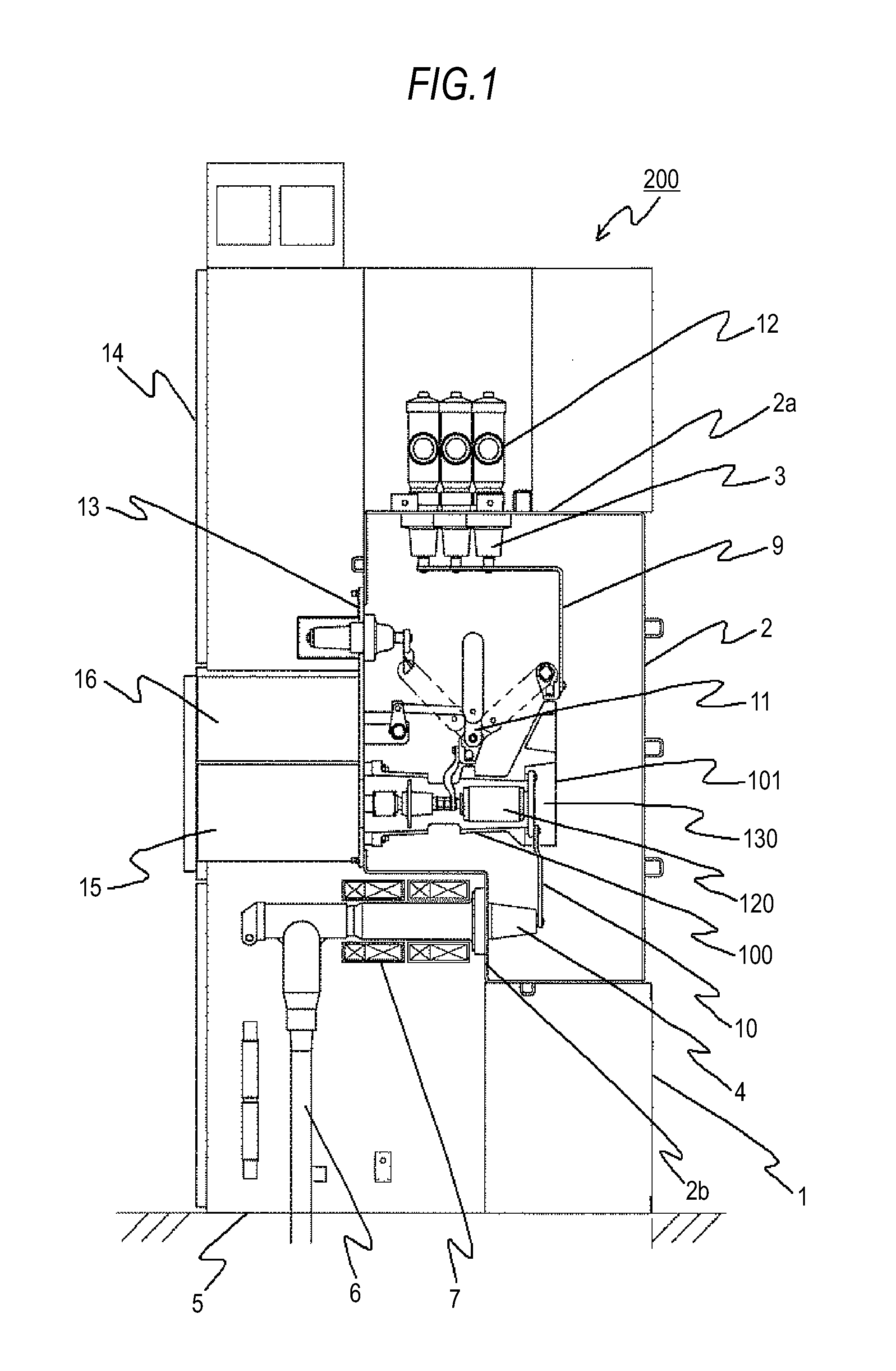
[0024]FIG. 1 is a cross section showing an overall configuration of a gas-insulated switchgear to which a power breaker according to one embodiment of the invention is applied.

[0025]As is shown in FIG. 1, amain circuit of the gas-insulated switchgear 200 is formed of a cable 6, a current detector 7, a cable bushing 4, a connecting member 10, breakers 100 as the power breaker, power disconnecting and grounding switches 11, a connecting member 9, a bus bushing 3, and buses 12.

[0026]Referring to FIG. 1, a breaker tank 2 filled with an insulating gas, such as a SF6 gas, is supported on a mount 1. The three-phase bus bushing 3 is provided to an upper endplate portion 2a of the breaker tank 2, and one bus 12 is connected to each phase of the bus bushing 3.

[0027]The cable bushing 4 is provided to a lower end plate portion 2b of the breaker tank 2. The three-phase cable 6 is provided to a base 5 and each phase of the three-phase cable 6 is connected to the cable bushing 4 via the current de...


PUM


Abstract

A power breaker incudes a fine motion mechanism portion having a chattering suppression portion formed of ring members and a ring member provided with sloping surfaces or curved surfaces at positions corresponding to one another in a state stacked up in a center axis direction, so that an impact generated upon collision of a movable electrode with a fixed electrode when a circuit is closed is trapped as a compression force. Hence, kinetic energy generated upon collision is consumed by energy absorption by friction due to a spring property of the ring members and a frictional force on the contact surfaces. It thus becomes possible to reduce a generation time of a chattering action.

Description

TECHNICAL FIELD[0001]The present invention relates to a power breaker, and more particularly, to a power breaker, such as a vacuum circuit breaker (VCB) in which a fixed electrode and a movable electrode allowed to come into contact with and separate from each other are brought into contact with each other by pressing one main contact against the other main contact in a movable direction.BACKGROUND ART [0002]There is a power breaker in the related art having a butt structure by which a fixed electrode and a movable electrode are abutted against each other, for example, as in a vacuum circuit breaker (VCB). Such a breaker becomes conductive when the both electrodes are brought into contact with each other by abutting respective main contacts against each other.[0003]The butt structure, however, may possibly give rise to chattering of the contacts when the circuit is closed upon collision of the both electrodes with a circuit closing speed.[0004]Patent Document 1 discloses a configura...

Claims


Application Information

Patent Timeline
IPC IPC(8): H01H3/60
CPCH01H3/60H01H33/666H01H33/66207H02B13/02
Inventor HASEGAWA, HIROSHIINOUE, TAKAKAZU
Owner MITSUBISHI ELECTRIC CORP
Why Eureka
Try Eureka