
Fixing rubber roller, fixing device and image forming apparatus incorporating the same

a technology of fixing device and rubber roller, which is applied in the direction of electrographic process apparatus, instruments, optics, etc., can solve the problems of high cost, complicated and large-sized, and cost-effective stay

Inactive Publication Date: 2008-06-03
SEIKO EPSON CORP
View PDF6 Cites 0 Cited by
  • Summary
  • Abstract
  • Description
  • Claims
  • Application Information

AI Technical Summary

Benefits of technology

The invention provides a fixing rubber roller that prevents the rubber layer from coming off the roller at the ends, an inexpensive fixing device that prevents tear of a sheet material or distortion of an unfixed toner image, and an image forming apparatus that includes the fixing device. The rubber layer is secured to the roller so as to cover the roller and a portion of the step portion, and the boundary between the first and second portions is rounded. The rubber layer is protruded from the step portion in an axial direction of the roller. The invention also provides a device for fixing a toner image on a recording medium, which includes a heat source and a pressure roller that come into contact with each other to form a nip portion through which the recording medium passes.

Problems solved by technology

However, since the rubber roller rotates while it is pressed against an opposite roller, both end faces of the rubber roller are bulgingly deformed by the pressure, and a problem arises, after use for a long time period, in that the end faces and the rubber layer comes off the circumferential surface of the core roller at the end faces and in the vicinity of the same.
However, there is a problem in that the method involves a complicated processing step for forming the rubber layer on the circumferential surface of the rigid core roller using press cure, cutting the layer into a predetermined length, and processing the layer into a chamfered shape over a predetermined length from the longitudinal ends of the layer.
In addition, there is another problem in that it is costly to stay with the processing of the rubber layer that is an elastic member because the process is difficult to perform and is not preferable in processing accuracy.
However, such a configuration will result in a high cost because it makes the device complicated and large-sized.

Method used


Image

  • Fixing rubber roller, fixing device and image forming apparatus incorporating the same
  • Fixing rubber roller, fixing device and image forming apparatus incorporating the same
  • Fixing rubber roller, fixing device and image forming apparatus incorporating the same

Examples


Embodiment Construction

[0123]Preferred embodiments of the invention will be described below in detail with reference to the accompanying drawings.

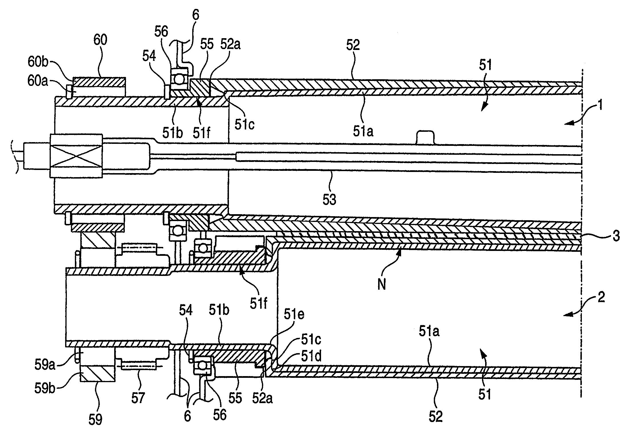
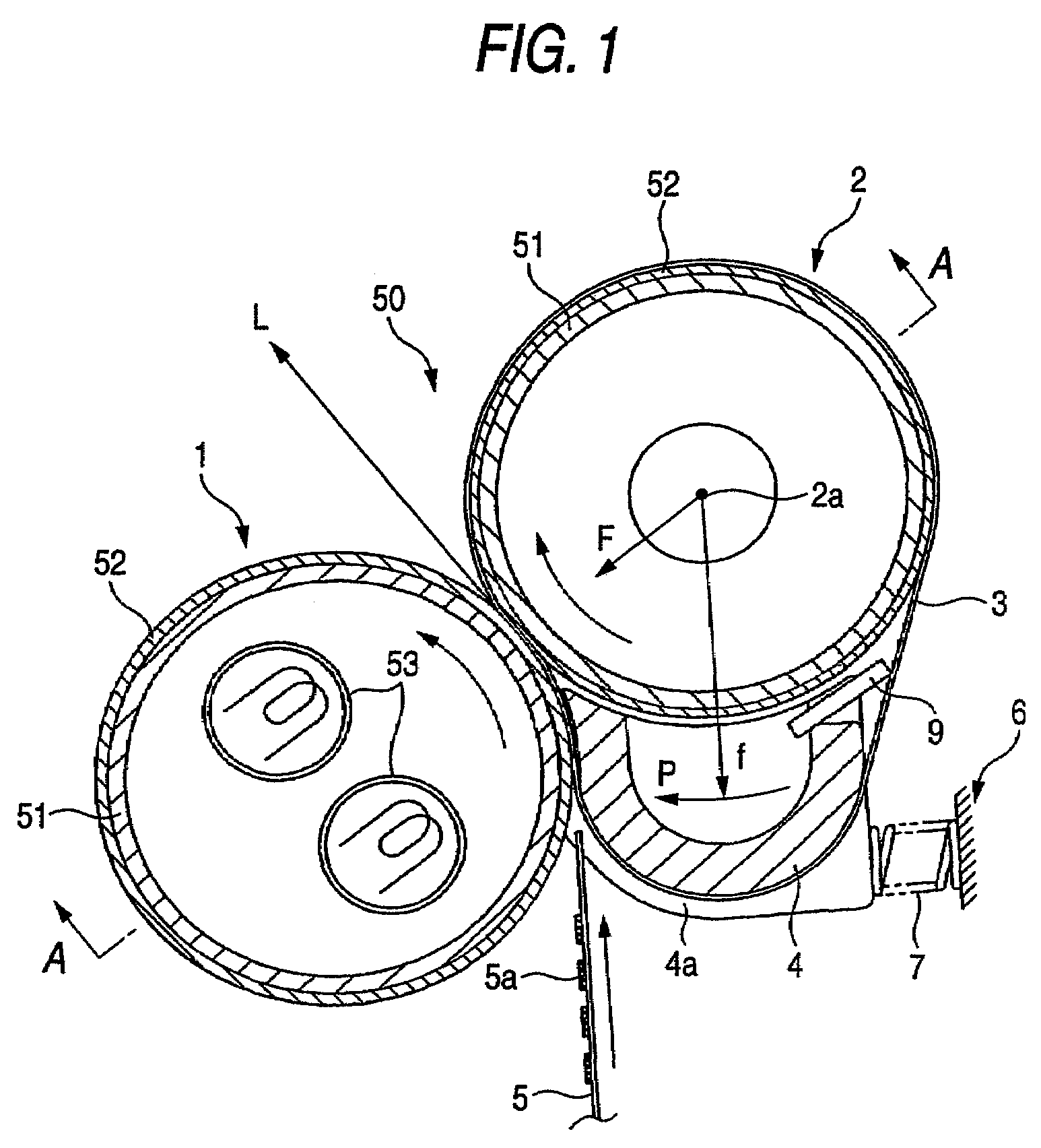
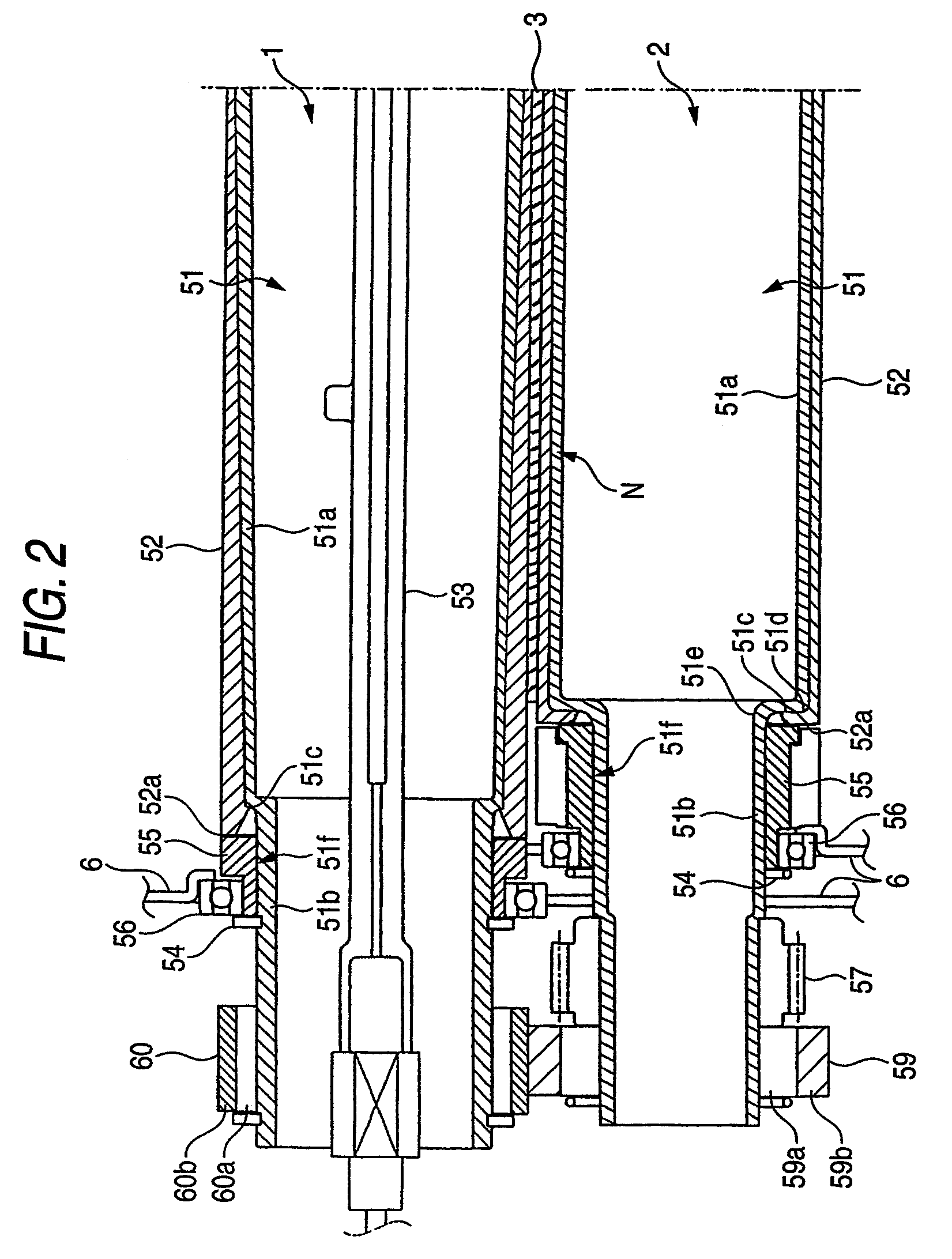
[0124]As shown in FIG. 1, a fixing device 50 according to a first embodiment of the invention is generally comprised of a heating roller 1, a pressure roller 2, a heat-resistant belt 3, and a belt stretcher 4.

[0125]The heating roller 1 is formed by securely bonding a rubber layer 52 having a thickness of about 0.4 mm to an outer circumferential surface of a rigid core roller 51 constituted by a metal pipe member having an outer diameter of about 25 mm and a thickness of about 0.7 mm. Two cylindrical halogen lamps of 1050 W as heat sources 53 are incorporated in the rigid core roller 51.

[0126]The pressure roller 2 is formed by securely bonding a rubber layer 52 having a thickness of about 0.2 mm to an outer circumferential surface of a rigid core roller 51 constituted by a metal pipe member having an outer diameter of about 25 mm and a thickness of about 0.7 mm. ...


PUM


Abstract

There is disclosed a device for fixing a toner image on a recording medium. A heat source is incorporated in a first roller. A heat-resistant belt member is stretched by a second roller and a stretcher and circulated therearound. The belt member is brought into contact with the first roller to form a nip portion therebetween through which the recording medium is passed. At least one of the first roller and the second roller is provided with a cylindrical core member and a rubber layer. The cylindrical core member is formed with a first portion having a first diameter, a second portion having a second diameter which is smaller than the first diameter, and a step portion continuously connecting the first portion and the second portion. The rubber layer is secured to an outer periphery of the core member so as to cover at least the first portion and a part of the step portion.

Description

BACKGROUND OF THE INVENTION[0001]The present invention relates to image forming apparatuses such as copiers, printers, and facsimile machines and, more particularly, to a fixing rubber roller and a fixing device incorporated in such image forming apparatuses.[0002]In a fixing device, normally, at least either a heating roller and a pressure roller is an elastic member or a rubber roller. The pressure roller is pressed against the heating roller with a predetermined pressure to form a nip. A transfer material having unfixed toner image is passed between the heating roller and the pressure roller to heat and fix the toner image. In general, the rubber roller is provided by heat-curing rubber on a circumferential surface of a rigid body or metal core roller to a predetermined thickness to mold the rubber and bond it to the core roller simultaneously.[0003]However, since the rubber roller rotates while it is pressed against an opposite roller, both end faces of the rubber roller are bul...

Claims


Application Information

Patent Timeline
Patent Type & Authority Patents(United States)
IPC IPC(8): G03G15/20
CPCG03G15/2053
Inventor ARUGA, TOMOE
Owner SEIKO EPSON CORP
Learn More