Wind turbine generating apparatus

a technology of wind turbines and generating equipment, which is applied in the direction of electric generator control, vessel construction, marine propulsion, etc., can solve the problems of insufficient volume of outside wind, easy corrosion or contamination of structures or devices inside the nacelle, and pressure loss, etc., and achieves compact and inexpensive configuration. simple, convenient

Inactive Publication Date: 2014-04-15
MITSUBISHI HEAVY IND LTD
View PDF33 Cites 4 Cited by
  • Summary
  • Abstract
  • Description
  • Claims
  • Application Information

AI Technical Summary

Benefits of technology

[0011]The present invention has been made in view of the aforementioned circumstances, and it is an object of the present invention to provide a wind turbine generating apparatus which can satisfactorily cool down heat generating devices installed inside a nacelle and a tower and can also protect the devices against corrosion or contamination with a simple, compact and inexpensive configuration.

Problems solved by technology

Thus, corrosion or contamination easily occurs in structures or devices inside the nacelle due to foreign substances such as moisture, salt content, and dust contained in the outside air, which is mechanically and electrically not preferable.
A pressure loss is caused when the filter is installed.
Thus, a sufficient volume of outside wind cannot be introduced.
However, there are also problems that the inner structure of the nacelle is complicated, and the air-cooling cooler inevitably has a large size to increase the entire size of the nacelle.
Moreover, the cooler is always exposed to outside air and thus needs to be sufficiently prepared against corrosion.
Accordingly, the construction cost of the wind turbine generating apparatus is increased due to the above factors.

Method used


Image

  • Wind turbine generating apparatus
  • Wind turbine generating apparatus
  • Wind turbine generating apparatus

Examples


first embodiment

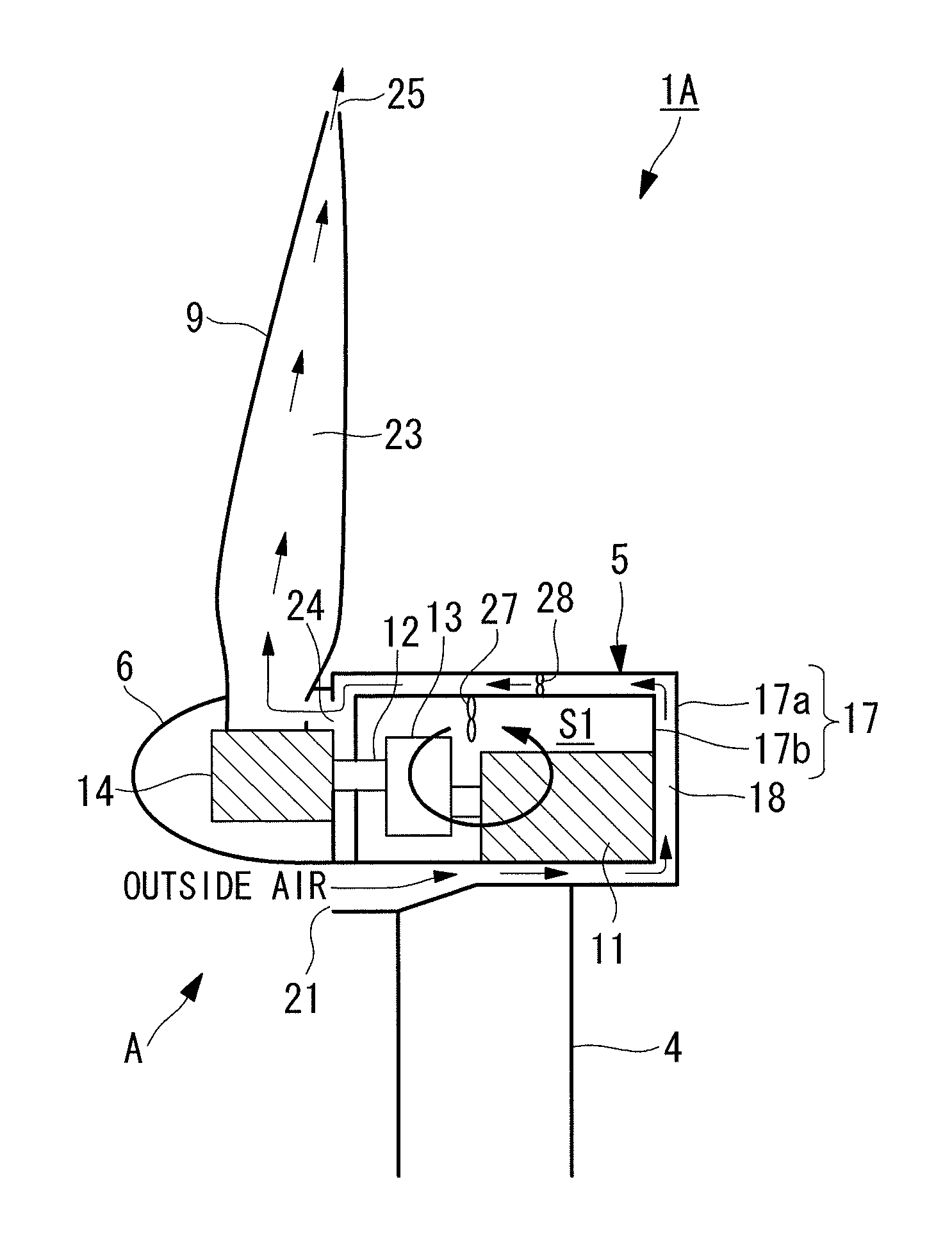
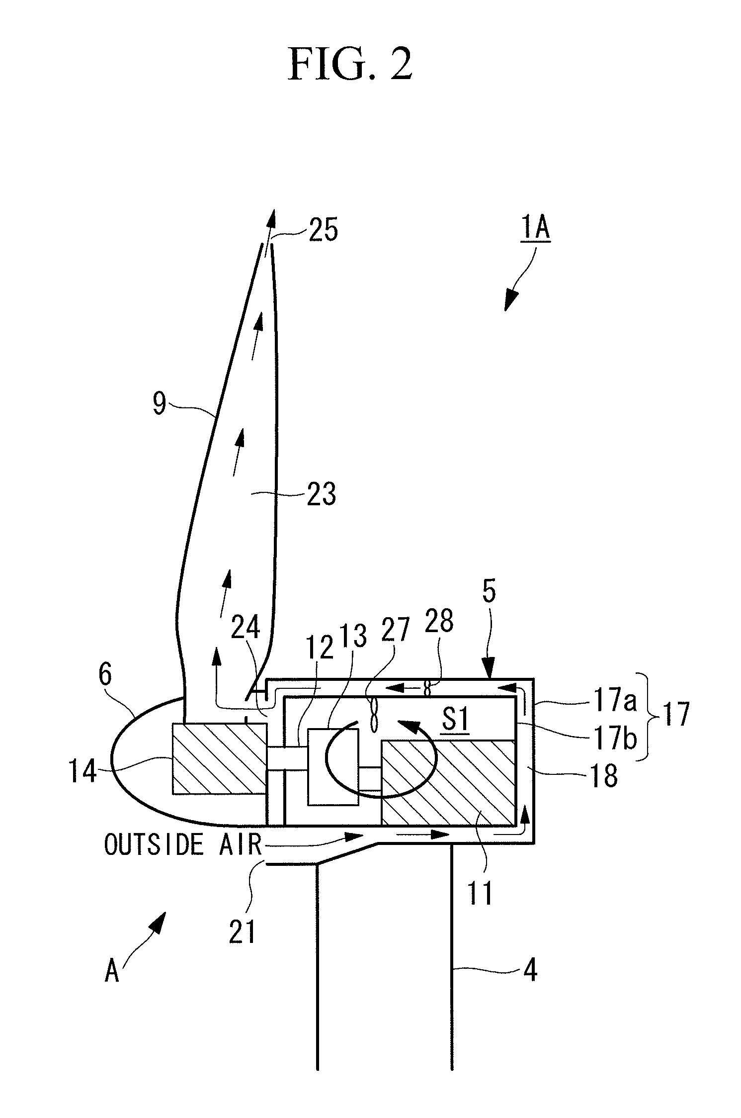
[0047]FIG. 2 is a schematic vertical sectional view of a wind turbine generating apparatus 1A according to a first embodiment of the present invention. The wind turbine generating apparatus 1A includes a cooling structure A. In the cooling structure A, a wall body 17 constituting the nacelle 5 has a double-walled structure with an outer wall 17a and an inner wall 17b provided inside the outer wall 17a with a space therebetween. The space between the outer wall 17a and the inner wall 17b is employed as a nacelle interior air passage 18. Outside air flows through the nacelle interior air passage 18 as cooling air. Although the entire wall body 17 has the double-walled structure, the wall body 17 may be partially double-walled.

[0048]The nacelle interior air passage 18 is completely isolated from the interior space S1 of the nacelle 5. The generator 11 installed as the heat generating device in the interior space S1 is provided adjacent to the nacelle interior air passage 18. To be more...

second embodiment

[0058]FIG. 3 is a schematic vertical sectional view of a wind turbine generating apparatus 1B according to a second embodiment of the present invention. The wind turbine generating apparatus 1B includes a cooling structure B. The cooling structure B differs from the cooling structure A in the above first embodiment only in that heat transferring means for transferring the heat of the interior space S1 the nacelle 5 to the nacelle interior air passage 18 is provided on the inner wall 17b that constitutes the nacelle interior air passage 18, and heat transferring means for transferring the heat generated from the pitch drive device 14 to the wind turbine interior air passage 23 is provided. The other components have the same configuration. For example, heat pipes 31 and 32 are employed as the heat transferring means.

[0059]The heat pipes 31 and 32 have a well-known structure in which a working fluid such as CFC substitutes is enclosed in a copper pipe, for example. The heat pipe 31 ins...

third embodiment

[0061]FIG. 4 is a schematic vertical sectional view of a wind turbine generating apparatus 1C according to a third embodiment of the present invention. The wind turbine generating apparatus 1C includes a cooling structure C. The cooling structure C differs from the cooling structure A in the first embodiment only in that an asperity shape 35 is provided on the inner wall 17b constituting the nacelle interior air passage 18. The other components have the same configuration as that of the cooling structure A. As a formation example of the asperity shape 35, the inner wall 17b may be formed by a corrugated sheet as shown in FIG. 5A, or a plurality of ribs 17c may be provided projecting from the outer surface of the inner wall 17b as shown in FIG. 5B.

[0062]Although it is shown in FIG. 4 that the longitudinal direction of grooves of the asperity shape 35 formed by the corrugated sheet is aligned with the width direction of the nacelle 5 (a direction perpendicular to the paper surface), t...


PUM


Abstract

A wind turbine generating apparatus includes a rotor head that rotates upon receiving outside wind on a wind turbine blade, a generator that generates electricity, and a nacelle interior air passage through which outside air flows isolatedly from an interior space of the nacelle.

Description

CROSS-REFERENCE TO RELATED APPLICATIONS[0001]This is a continuation of International Application PCT / JP2011 / 64978, with an international filing date of Jun. 29, 2011, which is hereby incorporated by reference herein in its entirety.BACKGROUND OF THE INVENTION[0002]1. Field of the Invention[0003]The present invention relates to a wind turbine generating apparatus which cools down heat generated by devices during operation by introducing outside air.[0004]2. Description of Related Art[0005]A typical wind turbine generating apparatus is an apparatus which generates electricity by causing a rotor head with wind turbine blades to rotate upon receiving wind power, increasing the speed of rotation by a gear box, and thereby driving a generator. The rotor head is attached at an end portion of a nacelle that is installed on a tower erected on the ground or the like so as to be movable in a yaw direction. The rotor head is supported rotatably around a rotational axis in a substantially-horizo...

Claims


Application Information

Patent Timeline
Patent Type & Authority Patents(United States)
IPC IPC(8): F03D11/02F03D9/00
CPCY02E10/726F05B2260/20F05B2260/64F05B2260/2241Y02E10/728F03D11/00Y02E10/722F05B2240/912F05B2240/14F03D9/25F03D80/60Y02E10/72
Inventor HIRAI, SHIGETOSATO, SHINSUKEISHIGURO, TATSUO
Owner MITSUBISHI HEAVY IND LTD
Why Eureka
Try Eureka