Imaging device and imaging system

Active Publication Date: 2012-12-13
CANON KK
View PDF2 Cites 2 Cited by
  • Summary
  • Abstract
  • Description
  • Claims
  • Application Information

AI Technical Summary

Benefits of technology

[0005]In the imaging device disclosed in Japanese Patent Laid-Open No. 2008-283331, the color of pixels to be read out from each channel varies depending on the operation mode. For example, referring to FIG. 10 in this document, there are two modes in reading out pixels in one row, namely a mode in which only signals indicating red are read out from Channel 1 and a mode in which both signals indicating red and signals indicating green are read out from Channel 1. In this way, if the color of pixels output fro

Problems solved by technology

In this way, if the color of pixels output from a single channel varies depending on the operation mode, the need arises to change the operation of a signal processi

Method used


Image

  • Imaging device and imaging system
  • Imaging device and imaging system
  • Imaging device and imaging system

Examples


Embodiment Construction

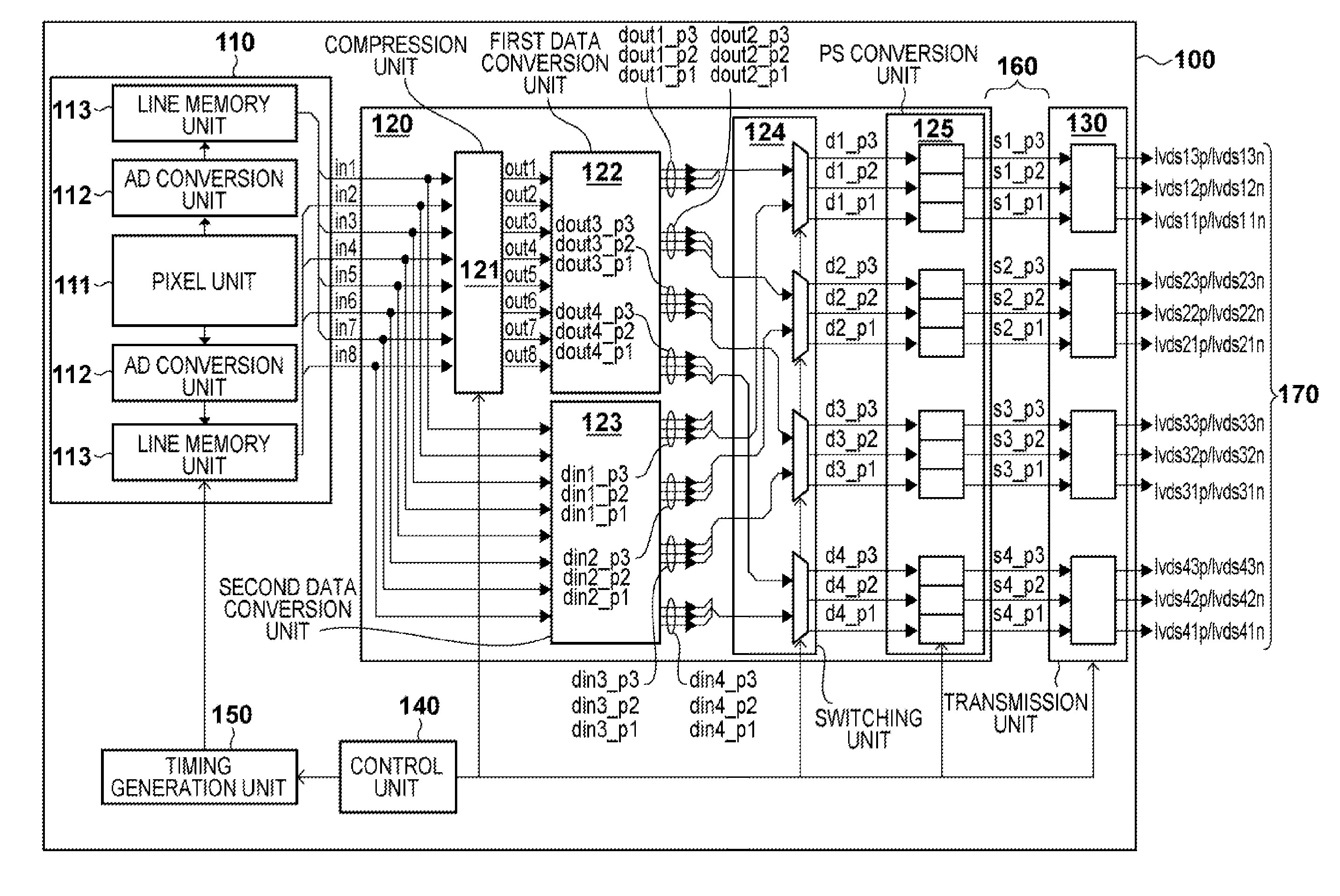
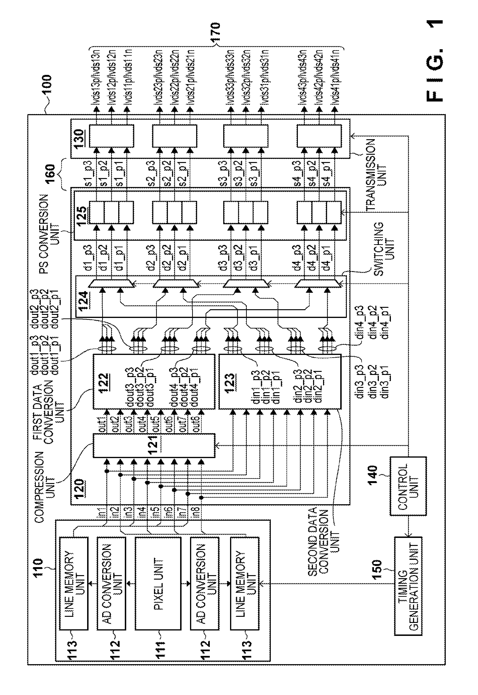
[0025]Various embodiments of the present invention will be described below with reference to the accompanying drawings. The following describes an exemplary overall arrangement of a solid-state imaging device 100 according to some embodiments with reference to FIG. 1. The solid-state imaging device 100 may include an imaging unit 110, a conversion unit 120, a transmission unit 130, a control unit 140, and a timing generation unit 150. Digital data indicating the pixel value of each pixel obtained by the imaging unit 110 is output to the conversion unit 120 as one of data pieces “in1” to “in8”. In the present embodiment, the conversion unit 120 and the transmission unit 130 are connected by 12 signal lines 160. The conversion unit 120 converts the data output from the imaging unit 110 and outputs the converted data to the transmission unit 130 as 12 data pieces “s1_p1” to “s4_p3”. The transmission unit 130 converts the transmission format of the data output from the conversion unit 1...


PUM


Abstract

An imaging device comprising an imaging unit that outputs digital data of a pixel value indicating one of colors for each pixel and a conversion unit that outputs from ports I pieces of the digital data that has been input from the imaging unit in a first mode and output from part of the ports J (J<I) pieces of digital data obtained from the I pieces of the digital data of the same color that has been input from the imaging unit in a second mode is provided. When outputting digital data of pixels of a single row in the imaging unit in the both modes, the conversion unit outputs digital data of a first color from a first port and outputs digital data of a second color from a second port.

Description

BACKGROUND OF THE INVENTION[0001]1. Field of the Invention[0002]The present invention relates to an imaging device and an imaging system.[0003]2. Description of the Related Art[0004]Reducing power consumption is one issue for conventional imaging devices. In an imaging device driven by a rechargeable battery, this issue is highly important because the power consumption of the device affects the shooting time or number of images captured per battery charging. There are also other issues such as increasing the number of pixels in a solid-state image sensor and increasing the frame rate (increasing the readout rate). Improving the operating frequency of readout from solid-state image sensors for high-speed readout is followed by an increase in power consumption, and thus reducing power consumption and improving the frame rate are the conflicting issues. In the solid-state imaging device disclosed in Japanese Patent Laid-Open No. 2008-283331, in order to cope with both of the issues, th...

Claims


Application Information

Patent Timeline
IPC IPC(8): H04N5/225
CPCH04N9/07H04N5/378H04N25/75H04N23/12
Inventor HAYASHI, HIDETOSHITAKENAKA, SHINTAROYAMAZAKI, TATSUHIKO
Owner CANON KK
Why Eureka
Try Eureka