Centrifugal blower and heat dissipation device incorporating the same

a centrifugal blower and heat dissipation device technology, applied in the direction of machines/engines, liquid fuel engines, lighting and heating apparatus, etc., can solve the problems of overheating of electronic components, further increasing costs, and complicating the design and manufacture of centrifugal blowers

Inactive Publication Date: 2011-07-28
FU ZHUN PRECISION IND SHENZHEN +1
View PDF106 Cites 7 Cited by
  • Summary
  • Abstract
  • Description
  • Claims
  • Application Information

AI Technical Summary

Benefits of technology

[0006]Increasing the amount of airflow provided by the centrifugal blower is an effective way to improve the heat dissipation efficiency of the heat dissipation device. Conventional ways of satisfying such requirement are to change the configurations of blades of the centrifugal blower and change the parameters of the motor of the centrifugal blower. However, such changes complicate the design and the manufacture of the centrifugal blower and further increase the cost thereof.

Problems solved by technology

If such heat is not quickly removed, these electronic components may overheat.
However, such changes complicate the design and the manufacture of the centrifugal blower and further increase the cost thereof.

Method used


Image

  • Centrifugal blower and heat dissipation device incorporating the same
  • Centrifugal blower and heat dissipation device incorporating the same
  • Centrifugal blower and heat dissipation device incorporating the same

Examples


Embodiment Construction

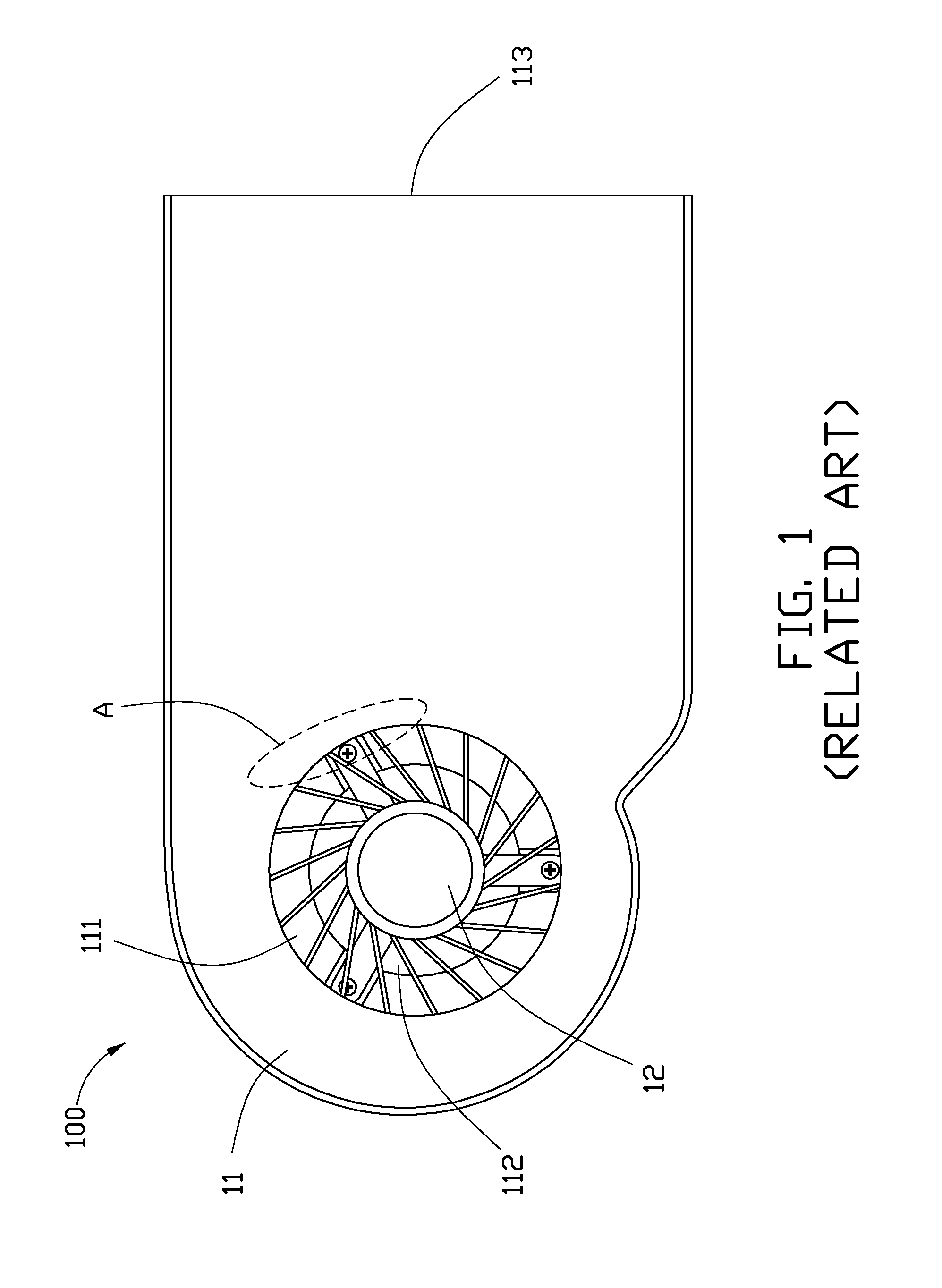
[0014]Referring to FIG. 1, a centrifugal blower 100 of the related art is shown. The centrifugal blower 100 includes a casing 11, and an impeller 12 rotatably disposed in an inner space of the casing 11. The casing 11 defines a top air inlet 111 in a top plate thereof, a bottom air inlet 112 in a bottom plate thereof, and an air outlet 113 in a sidewall thereof. In operation, the impeller 12 drives exterior air to enter the casing 11 via the top and bottom air inlets 111, 112, and then leave the casing 11 via the air outlet 113.

[0015]When the flow field of the airflow produced by the centrifugal blower was simulated by using computational fluid dynamics (CFD) software, it was found that a marked air-sucking phenomenon occurs at a region indicated by the closed broken line A. In other words, a sucking force at region A is stronger than at other regions of the top air inlet 111. Therefore, enlarging the area of the top air inlet 111 at region A to increase the amount of the air enteri...


PUM


Abstract

A heat dissipation device includes a centrifugal blower and fins. The centrifugal blower includes a housing defining a space therein, and an impeller rotatably disposed in the space of the housing. The housing includes a bottom plate, an opposite top plate defining an air inlet therein, and a sidewall disposed between the bottom plate and the top plate. The sidewall defines an air outlet therein. The top plate further defines an opening therein between the air inlet and the air outlet. The opening is spaced from the air inlet via a partition rib. The impeller is located corresponding to the air inlet of the top plate, for driving air to enter the housing via the air inlet and the opening and to leave the housing via the air outlet. The fins are disposed on the bottom plate and located at the air outlet of the centrifugal blower.

Description

BACKGROUND[0001]1. Technical Field[0002]The disclosure generally relates to centrifugal blowers; and more particularly to a centrifugal blower which can provide a large amount of airflow, and a heat dissipation device incorporating the centrifugal blower.[0003]2. Description of Related Art[0004]It is well known that heat is produced by electronic components, such as integrated circuit chips, during normal operation. If such heat is not quickly removed, these electronic components may overheat. Therefore, heat dissipation devices are often used to cool these electronic components.[0005]As an example, a heat dissipation device in the related art generally includes a fin assembly having a plurality of fins, and a centrifugal blower for creating an airflow through the fin assembly. The fin assembly is thermally connected to a heat generating electronic component such as a central processing unit (CPU) or a graphic processing unit (GPU) of a computer. Heat generated by the heat generatin...

Claims


Application Information

Patent Timeline
Patent Type & Authority Applications(United States)
IPC IPC(8): H01L23/467F01D1/02
CPCF04D29/582
Inventor ZHA, XIN-XIANGKUO, JER-HAUR
Owner FU ZHUN PRECISION IND SHENZHEN
Why Eureka
Try Eureka