

Tensioner
- Summary
- Abstract
- Description
- Claims
- Application Information
AI Technical Summary
Problems solved by technology
Method used
Image

Examples
Embodiment Construction
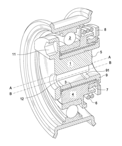
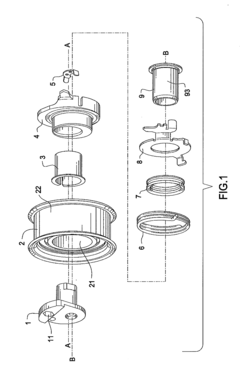
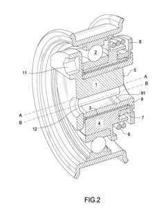
[0019]FIG. 1 is an exploded view of the tensioner. Pulley 2 engages a belt (not shown), for example on an engine accessory drive. Pulley 2 is journalled to an arm 4. Bearing 21 is disposed between pulley 2 and arm 4, thereby allowing pulley 2 to rotate about arm 4. Bearing 21 comprises a ball bearing as shown, but may also comprise a needle bearing or other suitable bearing known in the art.
[0020]Bushing 3 allows the arm 4 to smoothly rotate or pivot about sleeve 9. Sleeve 9 is rigidly connected to base 8. Bushing 3 creates some friction damping to prevent excessive movement of arm 4 that might otherwise be induced by an engine crankshaft angular vibration.
[0021]Arm 4 engages an inner race of bearing 21. The center of rotation for arm 4 about sleeve 9, axis A-A, is laterally offset from the center of rotation of pulley 2, axis B-B.
[0022]Arm 4 is urged against a belt by a torsion spring 6. Spring 6 is connected to base 8. Base 8 is statically connected to a mounting surface such as a...
PUM
 Abstract
Description
Claims
Application Information