Laser Square

a laser square and square technology, applied in the field of laser squares, can solve the problem of far too complex for the average hobbyist or home repair/remodeler

Inactive Publication Date: 2012-12-20
AMERICAN CRAFTS LC
View PDF9 Cites 13 Cited by
  • Summary
  • Abstract
  • Description
  • Claims
  • Application Information

AI Technical Summary

Benefits of technology

[0009]The present invention is a square with a laser indicator, which is particularly useful for a hobbyist to help her align photographs etc. to be mounted on pages. It has other uses, such as assisting a worker laying tiles to mark a line on a tile for cutting when the walls and corners are not precisely plumb.

Problems solved by technology

At least one feature that these and other laser squares known in the art have in common is that they are far too complex for the average hobbyist or home repair / remodeler.

Method used


Image

  • Laser Square
  • Laser Square
  • Laser Square

Examples


Embodiment Construction

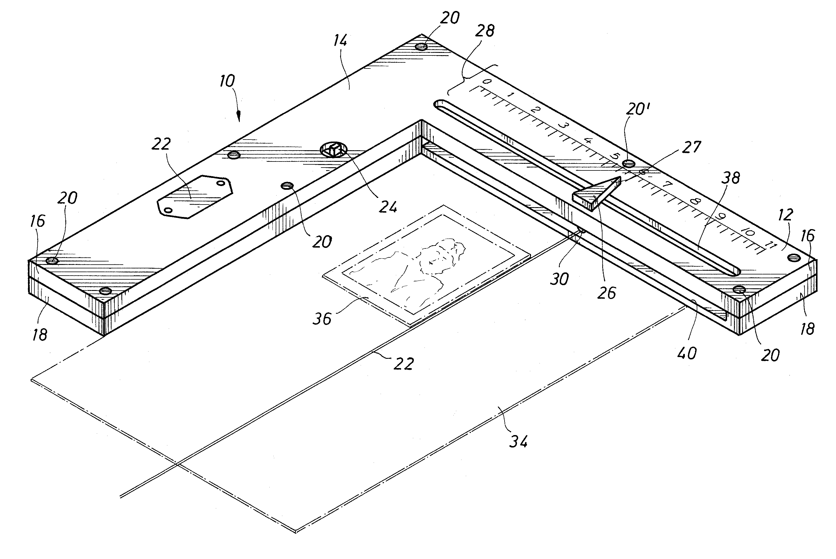
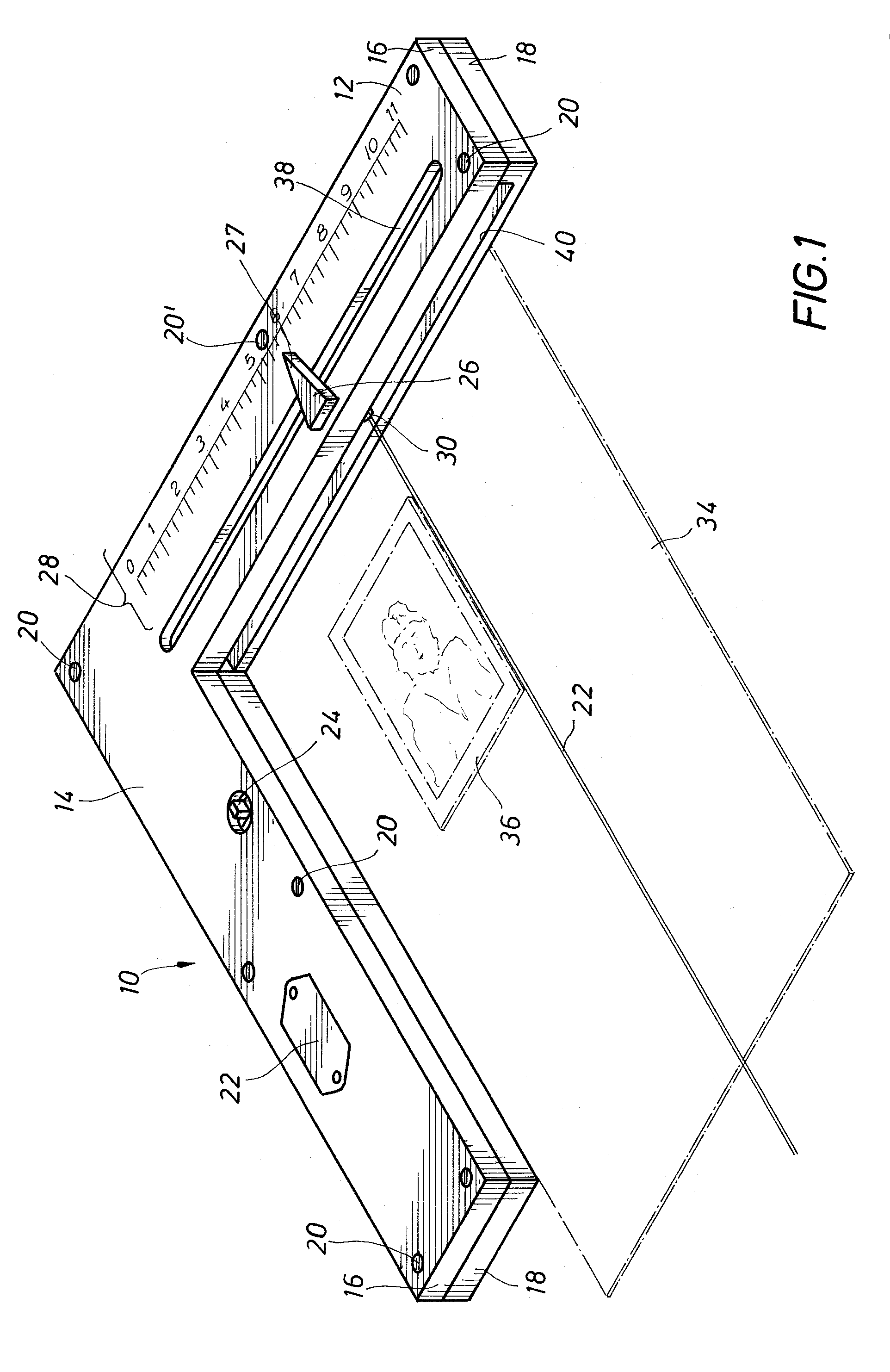
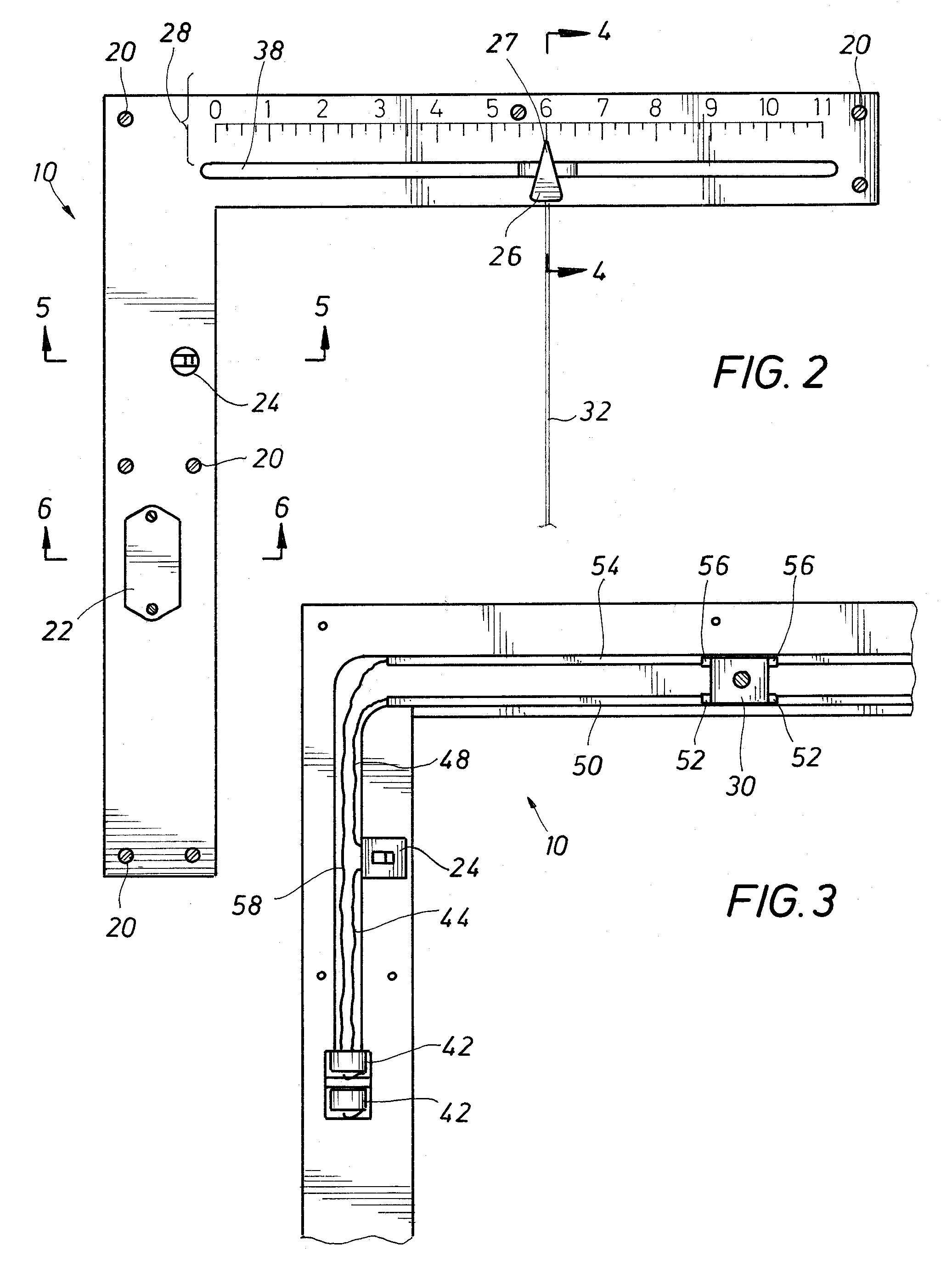
[0026]FIGS. 1, 2, and 3 illustrate a presently preferred embodiment of a laser square 10 constructed in accordance with the teachings of this invention. The laser square 10 includes a first arm, referred to herein as a scale arm 12, and a second arm, referred to herein as an alignment arm 14. The scale arm 12 and the alignment arm 14 are each preferably formed of a top half 16 and a bottom half 18. The top half 16 includes its portion of the scale arm 12 and alignment arm 14, formed together as a single article of manufacture. Similarly, the bottom half 18 includes its portion of the scale arm 12 and alignment arm 14, formed together as a single article of manufacture. The top half 16 and the bottom half 18 are joined together, such as with screws 20 or other appropriate means as desired, such as for example by gluing the top half and bottom half together. An adjustment screw 20′ operates to adjust the length of a light beam 32, described in more detail below.

[0027]The laser square ...


PUM


Abstract

A square includes a laser indicator and comprises a two-part body with a channel running between them defining a pair of perpendicular arms. The channel holds a cavity for a battery or other portable power source as part of an electrical circuit. One or both arms may include a scale as well as an elongate opening on the top of the arm for a handle to move a laser/indicator back and forth along the opening. The arms preferably include a pair of bus bars to conduct electricity from the power source to the laser. The second arm may also include a laser light source that is capable of moving in a direction parallel to the arm, as well as rotating in place.

Description

[0001]This application claims the benefit of U.S. Provisional Patent Application No. 61 / 446,713 filed Feb. 25, 2011.FIELD OF THE INVENTION[0002]The present invention relates generally to the field of laser squares and, more particularly, to a simple and robust laser square using a laser alignment feature. The invention further relates to a laser square using a first laser alignment element having transverse alignment while maintaining angular alignment and a second laser alignment element having both transverse and angular alignment.BACKGROUND OF THE INVENTION[0003]In U.S. Pat. No. 7,430,810; Sergyeyenko et al. illustrated a laser, square, protractor kit which has a laser marker with a housing. The housing has a first positioning member. The protractor has a base with a second positioning member which cooperates with the first positioning member to position the housing on the protractor base. The protractor base also includes a third positioning member. A framing square is coupled w...

Claims


Application Information

Patent Timeline
Patent Type & Authority Applications(United States)
IPC IPC(8): G01C15/12
CPCG01C15/12Y10S33/21G01B3/566
Inventor KELLY, JAMES H.
Owner AMERICAN CRAFTS LC
Why Eureka
Try Eureka