Adjustably attenuating ear plug

a technology of adjustable attenuation and ear plugs, which is applied in the field of ear plugs, can solve the problems of affecting the life, affecting the function of ear plugs, so as to improve the life, safety and effectiveness of ear plugs, and facilitate cleaning and maintenance. , the effect of convenient manipulation

Active Publication Date: 2012-12-20
BROWN INNOVATION
View PDF15 Cites 41 Cited by
  • Summary
  • Abstract
  • Description
  • Claims
  • Application Information

AI Technical Summary

Benefits of technology

[0005]Responsive to these and other concerns, the present invention recites an adjustably attenuating ear plug. The inventive plug is useful for selectively and gradually adjusting the exposure of the ear canal to an ambient environment. The invention is further useful for presenting an ear plug that fits and conforms more securely and comfortably within the ear canal in comparison to prior art ear plugs. Further, the inventive ear plug enabl

Problems solved by technology

Though long used to provide auditory attenuation and protection in high decibel or otherwise harmful environments, conventional ear plugs present various concerns in the art, including, for example, typically fixed configurations that offer limited variability.
Additionally, current ear plugs are often rectangular in shape, and as such are ill-fitted to the ear canal.
Adjustable

Method used


Image

  • Adjustably attenuating ear plug
  • Adjustably attenuating ear plug
  • Adjustably attenuating ear plug

Examples


first embodiment

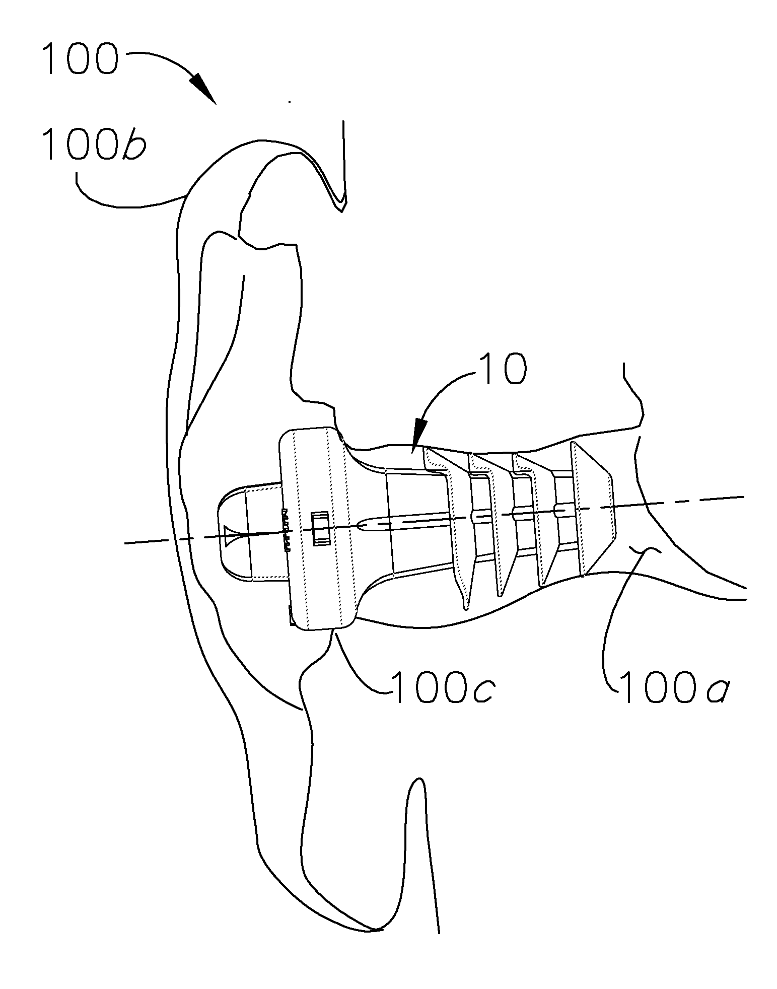
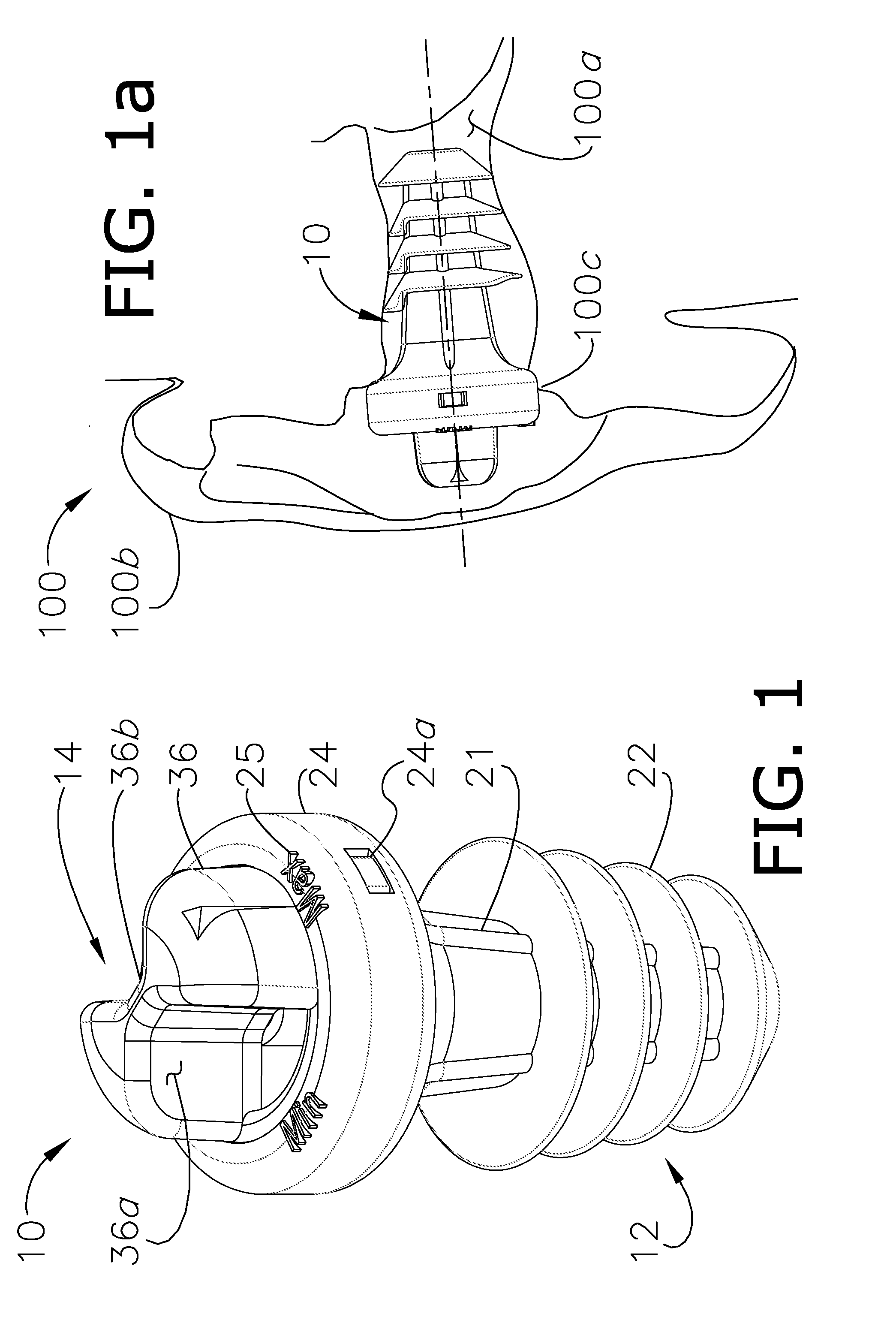
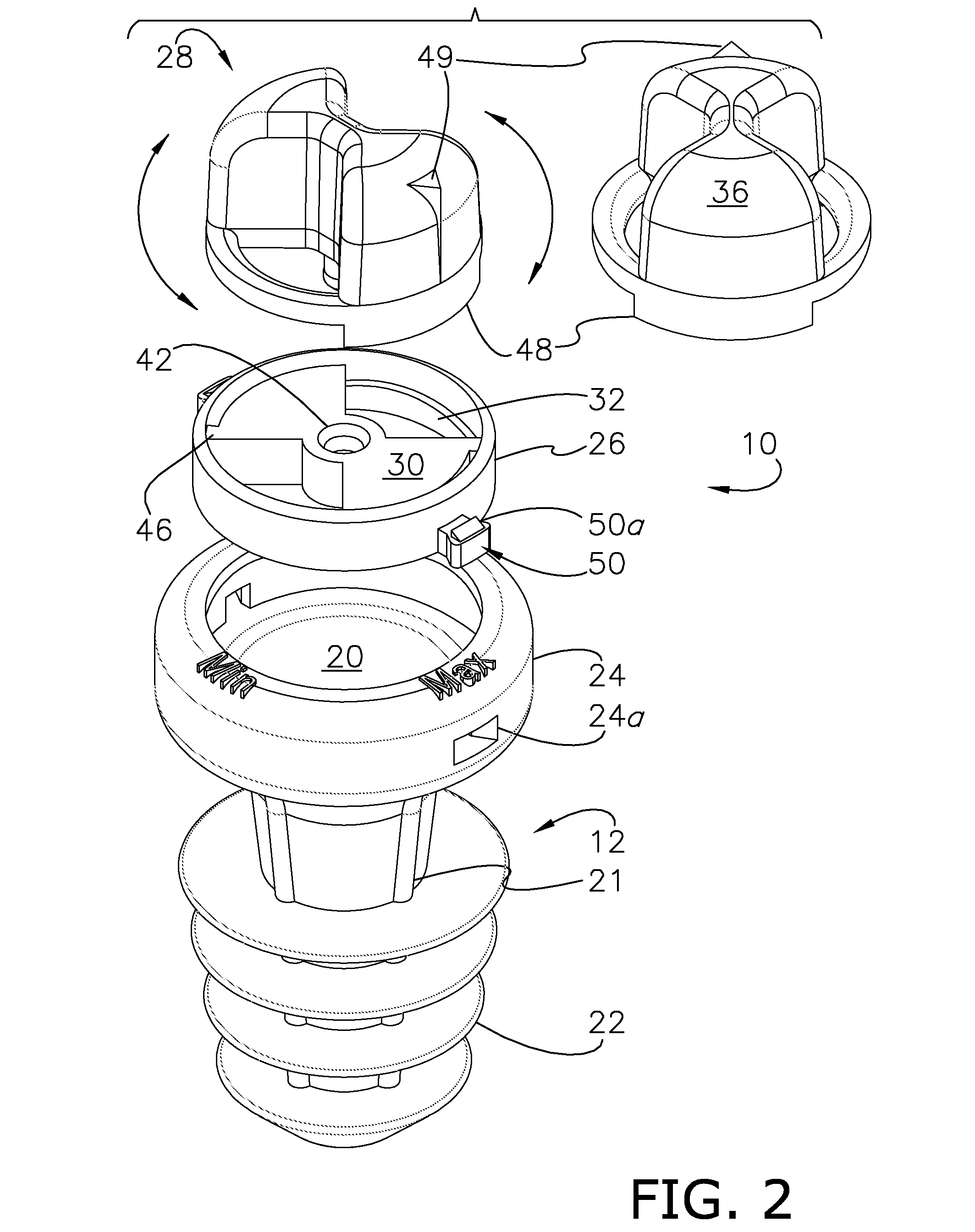
[0027]In a first embodiment, and as best shown in FIGS. 1-4, the disk 26 alternately defines at least one shield 30 and at least one hole 32, and more preferably, a plurality of shields 30 and holes 32. For example, the disk 32 may be divided into radial quarters, wherein the quarters alternatively define the holes 32 and shields 30. FIG. 2 also illustrates the increased thickness of the shields 30 (e.g., 0.050 inches (i.e., 0.127 cm)) compared to the remainder of the disk 26.

[0028]As best shown in FIGS. 4a and 4b, the knob 28 preferably defines first and second inlets 34, and includes a head 36 preferably defining a butterfly shaped configuration. The butterfly shaped configuration effects first and second sound collecting surfaces 36a,b. To reduce material, the knob 28 is preferably hollow, and as such, may be generally formed by a outer shell 38 having a thickness of 0.050 inches (i.e., 0.127 cm) and a central prong 40 (FIG. 3). The head 36 is of predetermined height (e.g., 0.225...

third embodiment

[0036]the inventive ear plug 10 is shown in FIGS. 6a-c, wherein the valve assembly 14 is configured to longitudinally space at least a portion of the knob 28 from the disk 26, and more particularly the inlet(s) 34 from the shield(s) 30. In this configuration, the assembly 14 defines a transmission 54 that converts the rotational displacement of the knob 28 into longitudinal displacement. For example, a series of stair-stepped ramps 56 having landings 58 corresponding to an incremental adjusted position may be defined by the disk 26, while the knob 28 defines a congruent and opposing arrangement (FIG. 6c). The knob 28 defines at least one inlet 34 (FIG. 6a) that engages a circular shield 30 defined by the disk 26 (FIG. 6b). More preferably, the shield 30 is compressible so as to effect sealed engagement with the inlet 34 at least in the lowermost position. Asides from the circular shield 30 and the ring formed by the ramps 56, the disk 26 is generally open (FIG. 6b), such that when t...


PUM


Abstract

An adjustably attenuating ear plug adapted for use in an ear canal, includes a flexible body, and a valve assembly further comprising a disk and knob translatable relative to the disk, wherein the knob defines at least one inlet, the disk alternately defines at least one shield and hole, and the inlet is alternatively aligned with the hole and shield to varying degrees, so as to selectively and variably expose the canal to the environment.

Description

BACKGROUND OF THE INVENTION[0001]1. Field of the Invention[0002]The present invention relates generally to ear plugs, and more particularly, to an ear plug having a manually adjustable valve assembly that enables the attenuation offered by the ear plug to be varied.[0003]2. Discussion of the Prior Art[0004]Though long used to provide auditory attenuation and protection in high decibel or otherwise harmful environments, conventional ear plugs present various concerns in the art, including, for example, typically fixed configurations that offer limited variability. Additionally, current ear plugs are often rectangular in shape, and as such are ill-fitted to the ear canal. Conventional ear plugs typically offer fixed sound attenuation, and must be completely removed from the canal for the user to hear. Adjustable plugs have been developed that offer selective exposure to the canal when in place; however, these measures have relied upon complex and / or cumbersome mechanisms, such as push...

Claims


Application Information

Patent Timeline
IPC IPC(8): G10K11/00
CPCA61F11/08G10K11/002H04R2460/11A61F2011/085A61F11/12A61F11/085
Inventor BROWN, THOMAS WILLIAM
Owner BROWN INNOVATION
Why Eureka
Try Eureka