Optical Density Sensor Calibration and Self Fixing

Inactive Publication Date: 2012-12-20
HEWLETT PACKARD DEV CO LP
View PDF8 Cites 8 Cited by
  • Summary
  • Abstract
  • Description
  • Claims
  • Application Information

AI Technical Summary

Problems solved by technology

One issue effecting print quality is the ability to ac...

Method used


Image

  • Optical Density Sensor Calibration and Self Fixing
  • Optical Density Sensor Calibration and Self Fixing
  • Optical Density Sensor Calibration and Self Fixing

Examples


Embodiment Construction

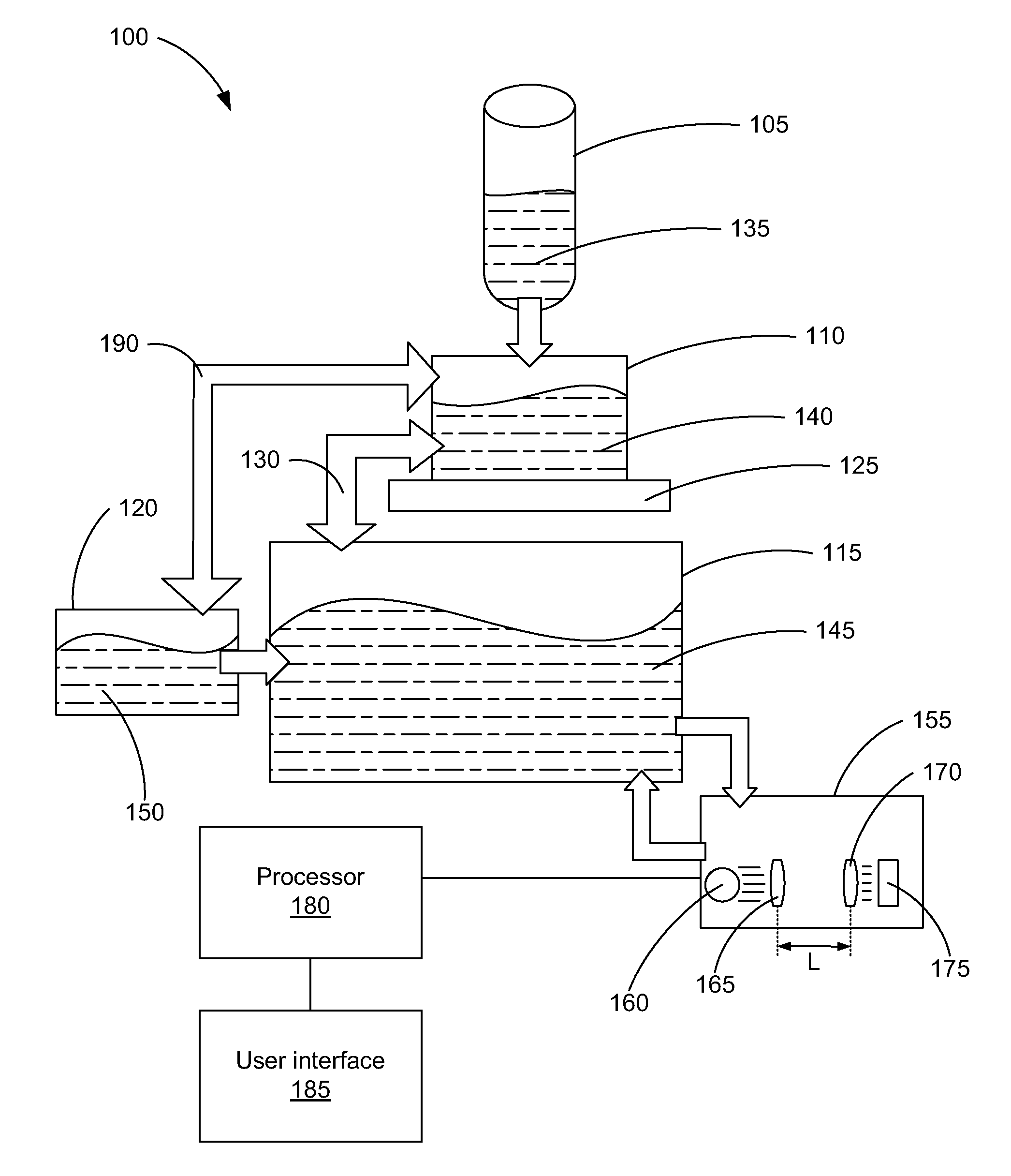
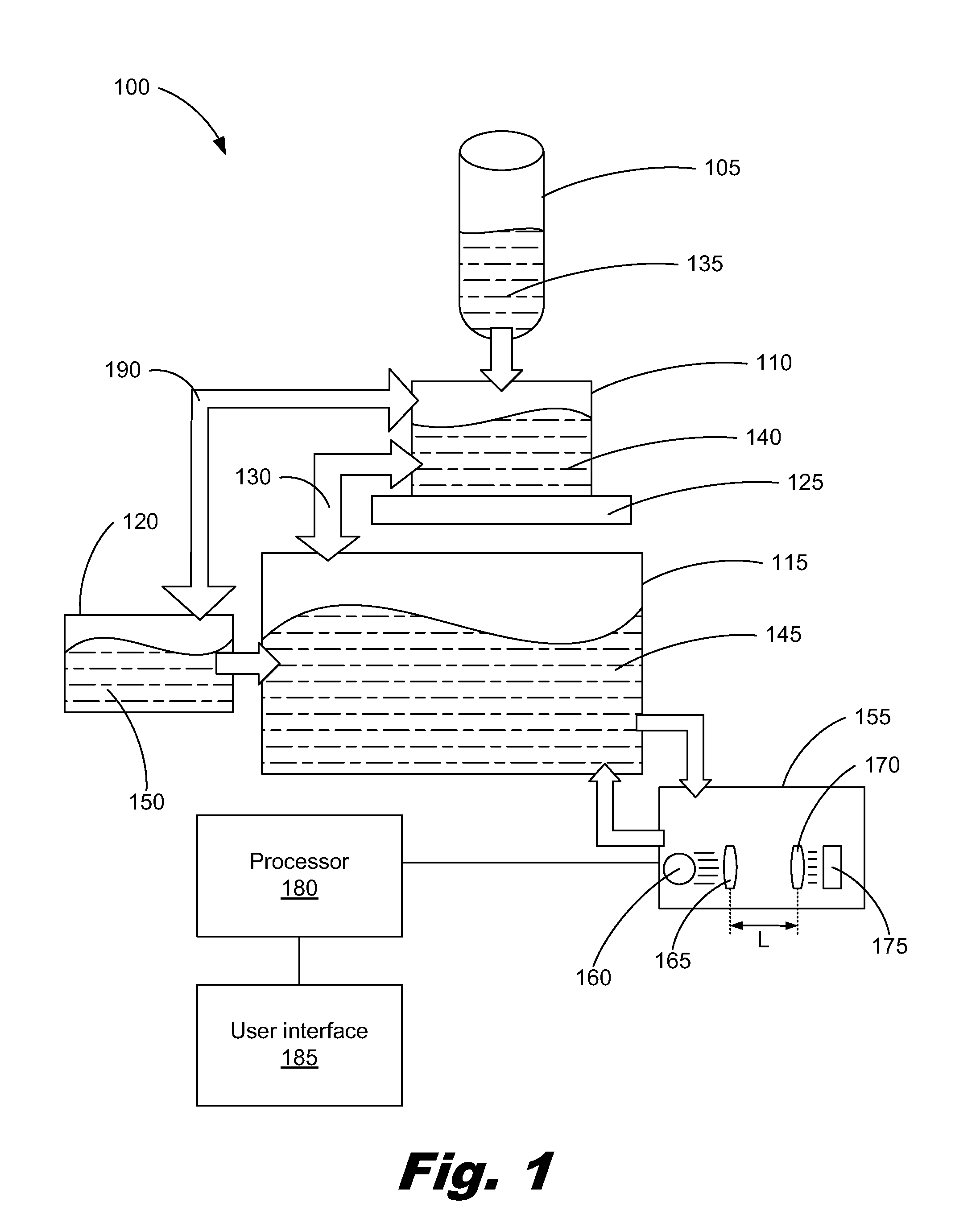
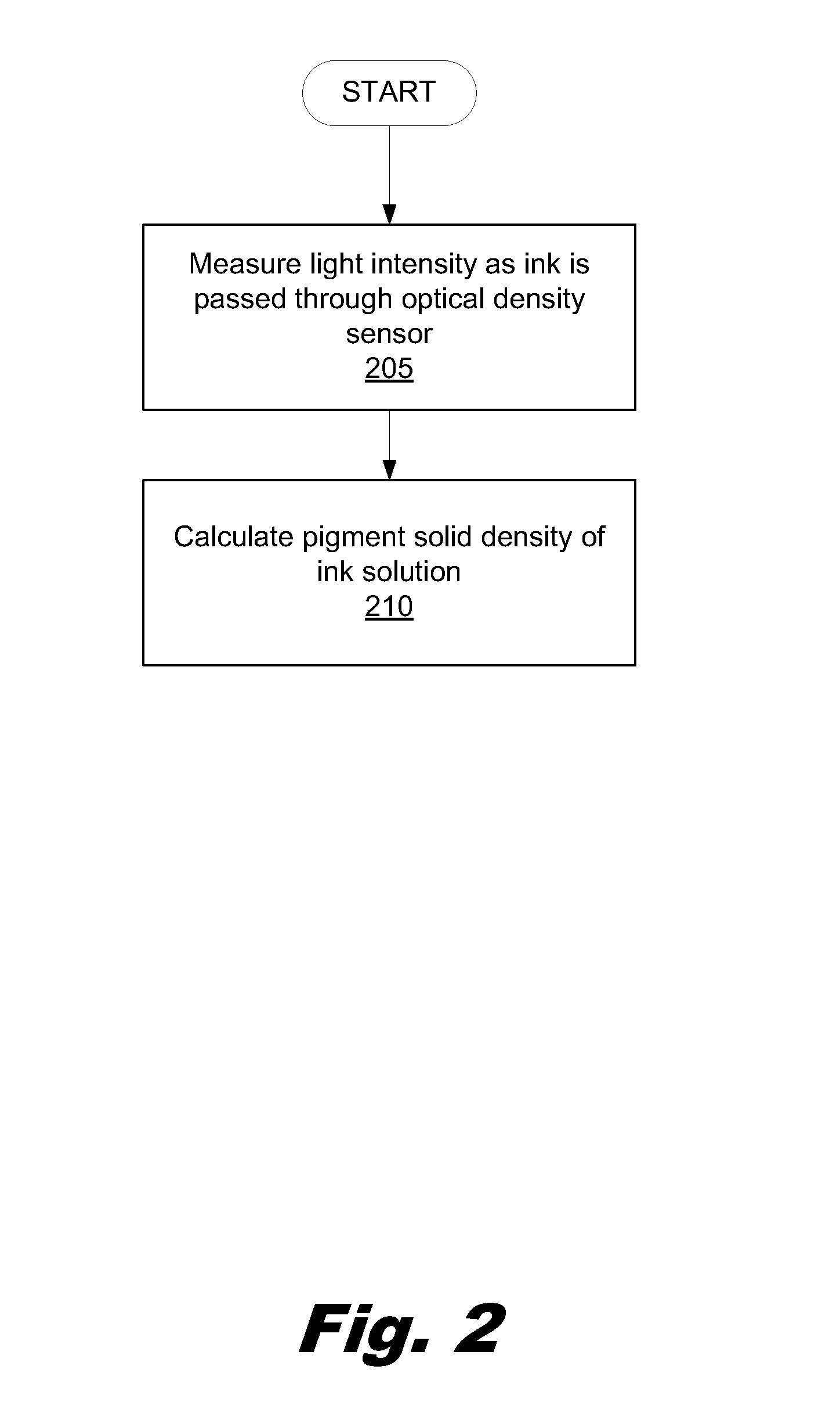
[0010]An optical density sensor uses a light source, a number of lenses and a photodetector to determine the ink pigment density of an ink solution. In order to measure the pigment density, the optical density sensor may pass an amount of ink in between a light source and a photodetector. The individual pigment particles within the ink, when passed through the light and in between a number of lenses, either absorb or reflect the light from the light source. Consequently, this prevents at least a portion of the light from reaching the photodetector. The light that is not blocked is able to reach the photodetector and the amount of light is measured by the photodetector. Through this process, the particle density of the ink may then be calculated.

[0011]However, the sensitive electrical and mechanical components of the optical density sensors may be unintentionally worn down or even damaged. The damage may be brought about during the fabrication process of the printing system or during...


PUM


Abstract

A method of calibrating an optical density sensor comprising calculating a first pigment solid density value of an ink solution using a current first electrical output signal value from a photodetector, a current second electrical output signal value from a photodetector, and a current lens gap value, calculating a second pigment solid density value of the ink solution using a previously measured first electrical output signal value, a previously measured second electrical output signal value, and a previously measured lens gap value, comparing the current first electrical output signal value, the current second electrical output signal value, and the current lens gap value with the previously measured first electrical output signal value, the previously measure second electrical output signal value, and the previously measured lens gap value, and comparing the first pigment solid density value with the second pigment solid density value.

Description

BACKGROUND[0001]One issue effecting print quality is the ability to accurately measure the pigment density within an ink solution. Accurate and consistent pigment density within the ink solution results in a more appealing printed product. In order to achieve accurate and consistent pigment density throughout the supply of ink within a printing device, an optical density sensor may be used.BRIEF DESCRIPTION OF THE DRAWINGS[0002]The accompanying drawings illustrate various examples of the principles described herein and are a part of the specification. The illustrated examples do not limit the scope of the claims.[0003]FIG. 1 is a diagram of an ink building system within a printer according to one example of principles described herein.[0004]FIG. 2 is a flowchart depicting a method of measuring, dynamically, an ink solution comprising an undetermined pigment solid density according to one example of the principles described herein.[0005]FIG. 3 is a flowchart depicting a method of dia...

Claims


Application Information

Patent Timeline
IPC IPC(8): G01N21/59
CPCG01N21/274G01N21/5907
Inventor SHEMER, ZVIGILAN, ZIVSHEMTOV, NIVHARUSH, SHLOMOLEVY, NATTYPORAT, AMIT
Owner HEWLETT PACKARD DEV CO LP
Why Eureka
Try Eureka