Damage isolation by shaped beam delivery in laser scribing process

a laser scribing and beam delivery technology, applied in the field of semiconductor processing, can solve the problems of patterning resist, inability to meet the requirements of production,

Active Publication Date: 2012-12-20
APPLIED MATERIALS INC
View PDF7 Cites 68 Cited by
  • Summary
  • Abstract
  • Description
  • Claims
  • Application Information

AI Technical Summary

Benefits of technology

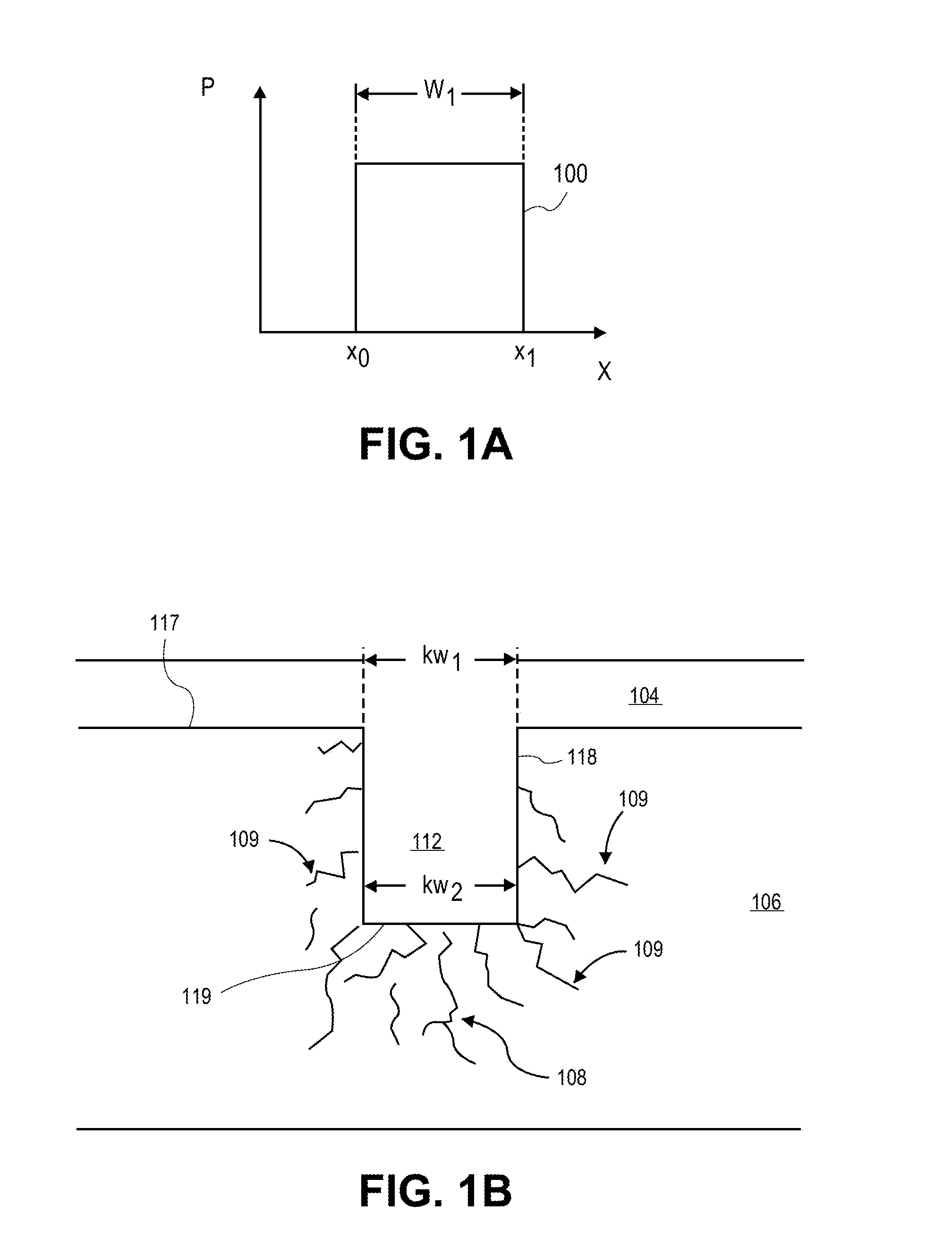
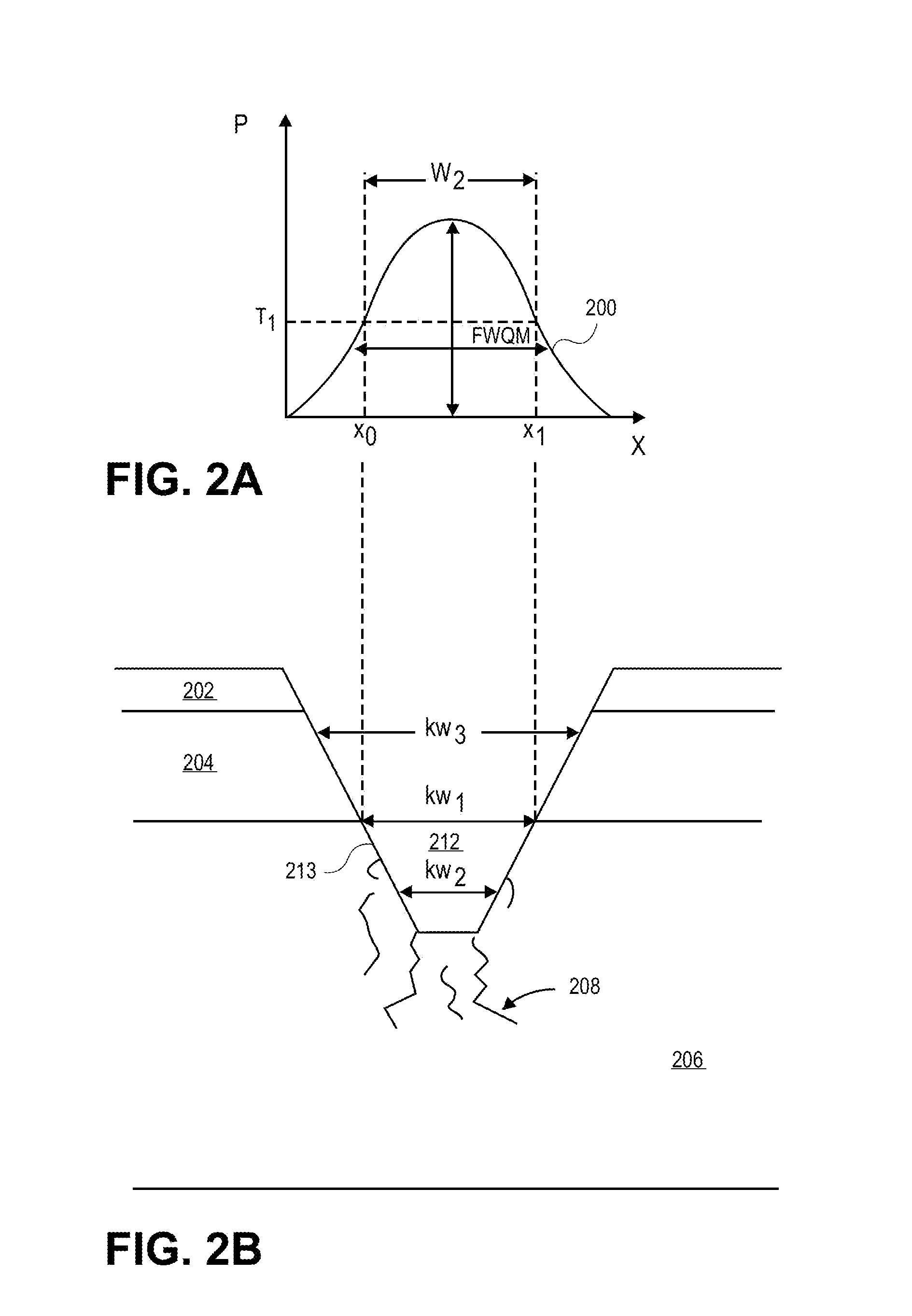
The patent describes a system that combines a laser and a plasma chamber on the same platform for cutting semiconductor substrates. The laser removes material with a centrally peaked laser beam, while the plasma chamber then etches through the substrate and separates the IC chips, removing any microcracks that may be generated during the laser ablation process. The laser scribe module includes a beam shaper to create the centrally peaked spatial power profile. The technical effect of this system is improved precision and efficiency in the cutting of semiconductor substrates.

Problems solved by technology

The technical problem addressed in this patent text is the difficulty in effectively dicing thin semiconductor substrates, such as those used in the formation of ICs, without causing damage or poor process quality. Current techniques such as scribing and sawing have limitations in achieving precise control over the separation of the substrate, which can result in issues such as microcrack formation or delamination between layers. Plasma dicing has also been explored as a potential solution, but it is costly and has limitations in processing interconnect metals such as copper.

Method used


Image

  • Damage isolation by shaped beam delivery in laser scribing process
  • Damage isolation by shaped beam delivery in laser scribing process
  • Damage isolation by shaped beam delivery in laser scribing process

Examples


Embodiment Construction

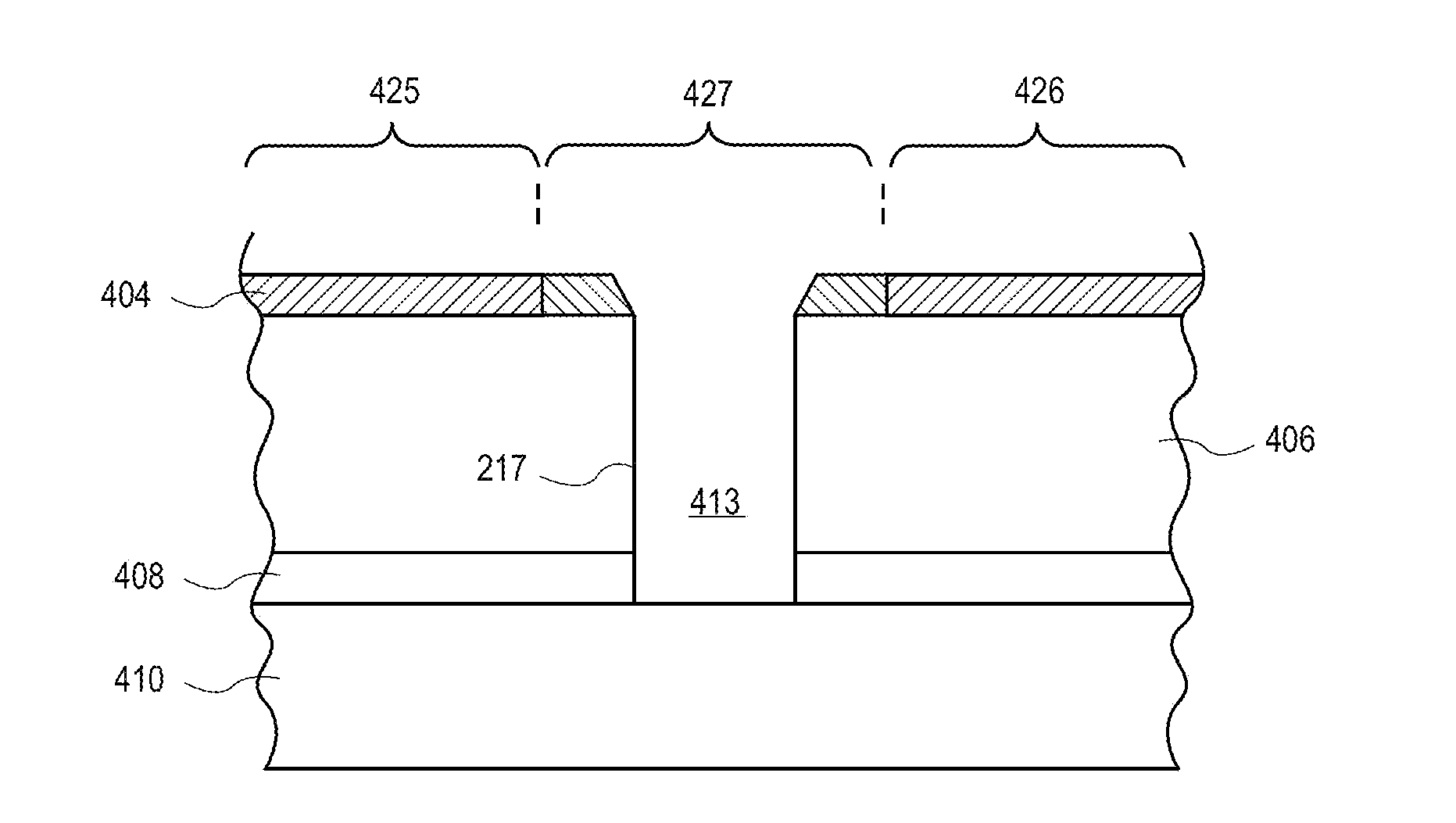
[0024]Methods of dicing substrates, each substrate having a plurality of ICs thereon, are described. In the following description, numerous specific details are set forth, such as femtosecond laser scribing and deep silicon plasma etching conditions in order to describe exemplary embodiments of the present invention. However, it will be apparent to one skilled in the art that embodiments of the present invention may be practiced without these specific details. In other instances, well-known aspects, such as IC fabrication, substrate thinning, taping, etc., are not described in detail to avoid unnecessarily obscuring embodiments of the present invention. Reference throughout this specification to “an embodiment” means that a particular feature, structure, material, or characteristic described in connection with the embodiment is included in at least one embodiment of the invention. Thus, the appearances of the phrase “in an embodiment” in various places throughout this specification ...


PUM

PropertyMeasurementUnit
Fractionaaaaaaaaaa
Timeaaaaaaaaaa
Thicknessaaaaaaaaaa

Abstract

Methods and apparatuses for dicing substrates by both laser scribing and plasma etching. A method includes laser ablating material layers, the ablating by a laser beam with a centrally peaked spatial power profile to form an ablated trench in the substrate below thin film device layers which is positively sloped. In an embodiment, a femtosecond laser forms a positively sloped ablation profile which facilitates vertically-oriented propagation of microcracks in the substrate at the ablated trench bottom. With minimal lateral runout of microcracks, a subsequent anisotropic plasma etch removes the microcracks for a cleanly singulated chip with good reliability.

Description


Claims


Application Information

Patent Timeline
Owner APPLIED MATERIALS INC
Why Eureka
Try Eureka