Communication apparatus and communication method

a communication apparatus and communication method technology, applied in the field of communication apparatus and communication method, can solve the problems of difficult to bring the antennas accurately close to each other, the antenna output cannot be increased, and the difficulty of accurately indicating the position

Inactive Publication Date: 2012-12-20
SOVEREIGN PEAK VENTURES LLC
View PDF5 Cites 46 Cited by
  • Summary
  • Abstract
  • Description
  • Claims
  • Application Information

AI Technical Summary

Benefits of technology

[0009]The present invention has been created to resolve the above-described problems and it is an object thereof to provide a communication apparatus and a communication method that can easily indicate the position of the antenna incorporated in the communication apparatus to the user and align the antenna of the communication apparatus with the antenna of an external device.
[0012]In accordance with the present invention, the position of the loop antenna is displayed on the basis of the antenna position information stored in the position information storing unit. Therefore, the position of the antenna incorporated in the communication apparatus can be indicated to the user, and the antenna of the communication apparatus can be easily aligned with the antenna of the external device.

Problems solved by technology

Therefore, when the user performs communication between two radio communication devices, it is difficult to bring the antennas accurately close to each other.
In particular, with the RFID incorporated in a cellular phone, the antenna output cannot be increased.
Therefore, the antennas should be aligned in the units of several millimeters, and it is difficult to bring the antennas accurately close to each other.
However, although the abovementioned Patent Literature 1 and Patent Literature 2 disclose the feature of displaying the antenna position, those documents do not disclose the feature of storing the information representing the antenna position.

Method used


Image

  • Communication apparatus and communication method
  • Communication apparatus and communication method
  • Communication apparatus and communication method

Examples


embodiment 1

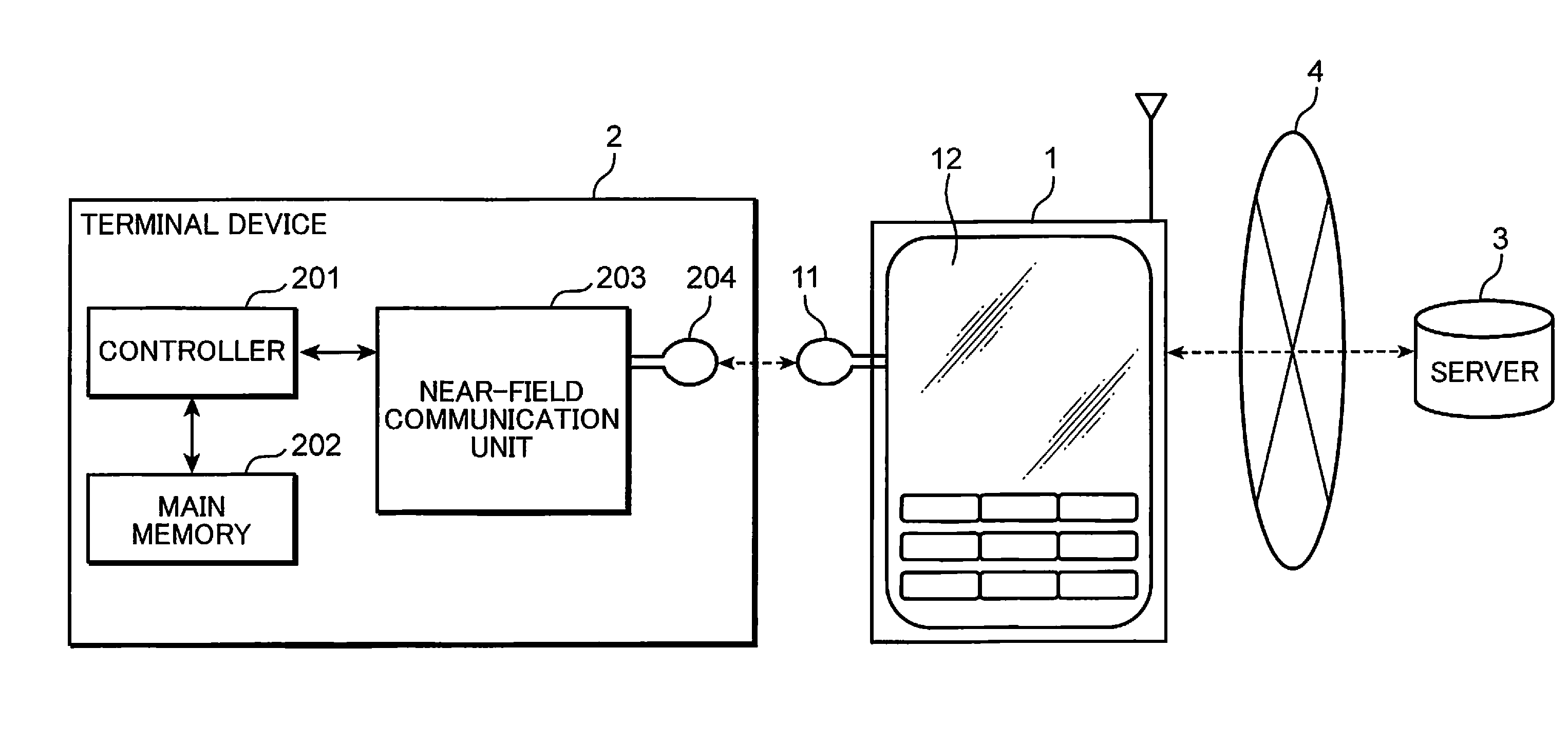
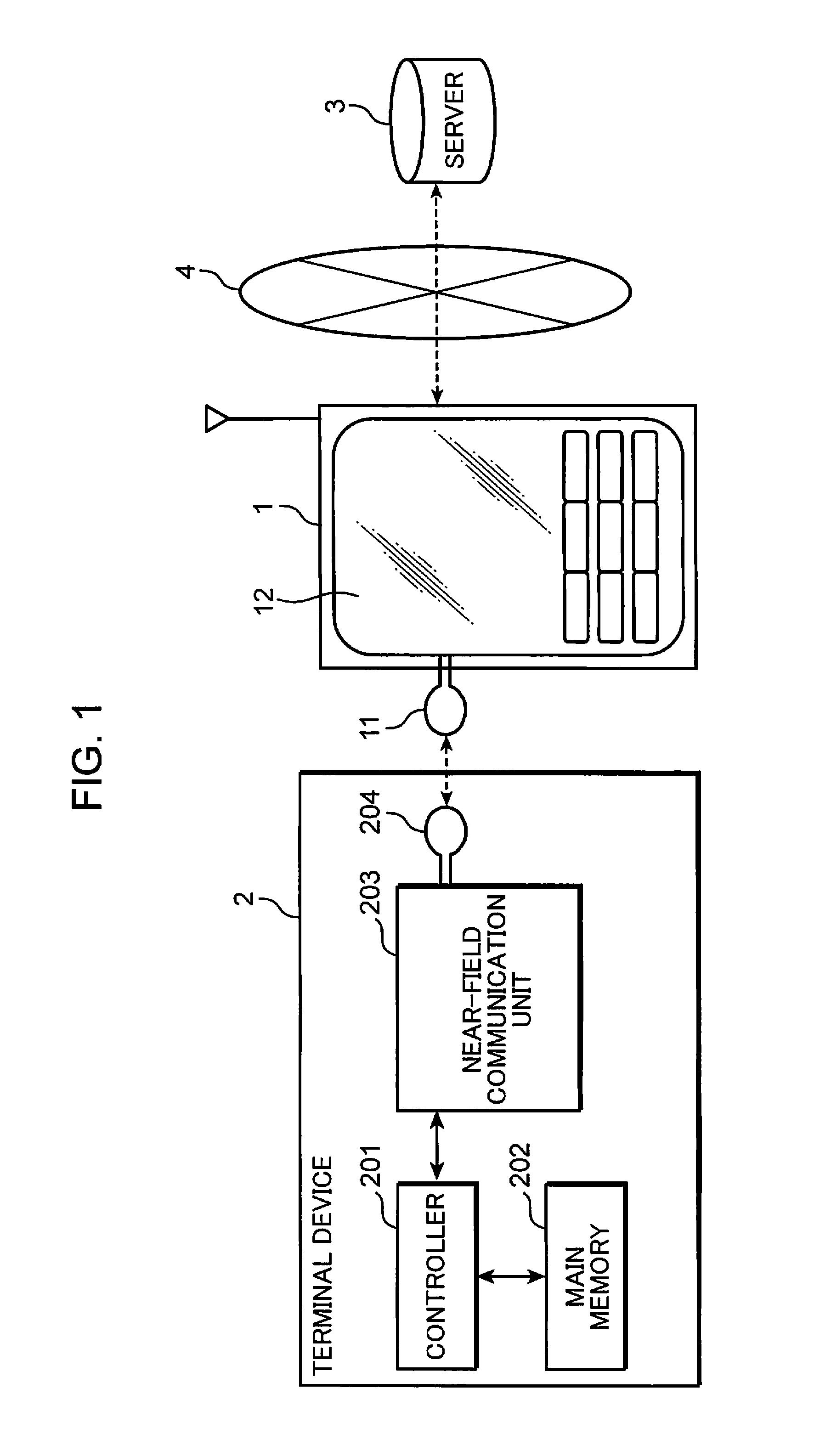
[0032]In Embodiment 1, a portable device provided, for example, with a RFID reader / writer is brought close to a terminal device provided with a RFID, terminal device information representing information on the terminal device including ID or the like is read from the terminal device, information on the portable device itself is added to the terminal device information that has been read by the portable device, and the resultant information is transmitted to a server. As a result, for example, the terminal device information can be registered in a database on the server in association with the portable device information.

[0033]User registration operations such as the registration of mail address in a server and the registration of a production number in a server have been conventionally performed by direct input by the user. As a result, the number of terminal devices registered in the server is small due to the complexity of input processing operation. By contrast, in the portable d...

embodiment 2

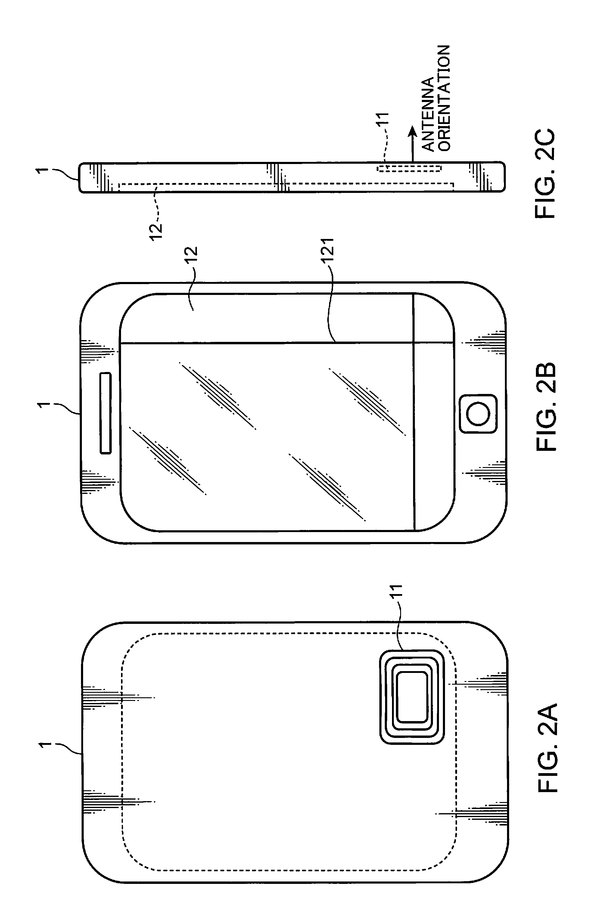
[0084]The communication system of Embodiment 2 of the present invention will be described below. In Embodiment 2, a guide pattern image of the same shape as the guide pattern representing the position of the loop antenna mounted on the terminal device is displayed at the position of the loop antenna mounted on the portable device.

[0085]FIG. 7 illustrates the internal configuration of the portable device in Embodiment 2 of the present invention. The configuration of the communication system in Embodiment 2 of the present invention is identical to the configuration of the communication system in Embodiment 1 and the explanation thereof is herein omitted.

[0086]A portable device 1 shown in FIG. 7 is provided with a loop antenna 11, a display unit 12, a system control unit 13, a memory unit 14, a near-field communication unit 15, an operation unit 16, a guide display control unit 17, a posture detection unit 18, a mobile network communication unit 19, and an antenna 20. The memory unit 1...

embodiment 3

[0116]The communication system of Embodiment 3 of the present invention will be described below. In Embodiment 3, the position of the loop antenna is displayed in superposition on the picked-up image of the orientation of the loop antenna.

[0117]FIG. 12 illustrates the internal configuration of the portable device in Embodiment 3 of the present invention. The configuration of the communication system in Embodiment 3 of the present invention is identical to the configuration of the communication system in Embodiment 1 and the explanation thereof is herein omitted.

[0118]A portable device 1 shown in FIG. 12 is provided with a loop antenna 11, a display unit 12, a system control unit 13, a memory unit 14, a near-field communication unit 15, an operation unit 16, a guide display control unit 17, a posture detection unit 18, a mobile network communication unit 19, an antenna 20, an image acquisition unit 21, and a pattern identification unit 22. The memory unit 14 is provided with a portab...


PUM


Abstract

The present invention provides a communication apparatus and a communication method that can easily indicate the position of the antenna incorporated in the communication apparatus to a user and can align the antenna of the communication apparatus with the antenna of an external device. A portable device (1) includes a loop antenna (11) for performing near-field communication, a display unit (12) provided on a side of the portable device (1) opposite the orientation of the loop antenna (11), and an antenna position information storing unit (142) that stores antenna position information representing the position of the loop antenna (11) in the portable device (1). The display device (12) displays the position of the loop antenna (11) on the basis of the antenna position information stored in the antenna position information storing unit (142).

Description

TECHNICAL FIELD[0001]The present invention relates to a communication apparatus and a communication method for performing communication with an external device by using near-field communication.BACKGROUND ART[0002]A technique for performing near-field communication between devices by using RFID (Radio Frequency Identification) has been suggested. In the near-field communication, the communication distance is short, and it is necessary to bring the antennas of two radio communication devices close to each other. A mark representing the position of the antenna is provided on the surface where the antenna of the radio communication device is mounted, and the user performs communication between the two radio communication devices by bringing the marks of two radio communication devices close to each other.[0003]The mark indicating the position of the antenna is hidden in the shade of the radio communication device when the two radio communication devices are brought close to each other....

Claims


Application Information

Patent Timeline
Patent Type & Authority Applications(United States)
IPC IPC(8): H04B5/00H04M1/72412H04M1/724
CPCH01Q1/125H01Q1/2216H01Q1/243H04M1/7253H04M2250/04H01Q7/00H04M1/72519H04B5/0081H04B5/0062H04M2250/52H04M1/72412H04M1/724
Inventor YAMAOKA, MASARUMATSUMOTO, MICHIHIROOHIRA, TOMOAKIOHNISHI, TOSHIAKISAKATA, TSUYOSHI
Owner SOVEREIGN PEAK VENTURES LLC
Why Eureka
Try Eureka