System and method for bone preparation for an implant

a bone preparation and implant technology, applied in the field of bone preparation for implants, can solve the problems of difficult to ascertain the amount of interference fit for application, the varying quality of the operating room, and the difficulty of orthopaedic surgeons in the operating room, and achieve the effect of improving the quality of the bone preparation

Active Publication Date: 2012-12-20
OMNILIFE SCI INC
View PDF8 Cites 76 Cited by
  • Summary
  • Abstract
  • Description
  • Claims
  • Application Information

AI Technical Summary

Benefits of technology

[0018]In a third aspect, the present invention provides a flexible system that gives a surgeon the ability to intra-operatively customize bone cuts according to the surgeon's preference and/or individual

Problems solved by technology

The amount of interference fit to apply, however, is difficult to ascertain and often determined by empirical methods with the benefit of intra-operative evaluations of the patient's bone.
One of the challenges orthopaedic surgeons face in the operating room is the varying quality of bone they are presented with at surgery.
Patients undergoing joint replacement surgery typically suffer from degenerative conditions that can alter bone quality.
For example, upon exposing the patient's joint and bones, the surgeon may encounter bone that is very poor in quality, having a relatively low density or high porosity.
Hence, when bone cuts are prepared in the same fashion for all patients, the resulting tightness or degree of the fit can vary from one patient to another depending upon the bone quality, which may ultimately impact the overall short term and long term success of the implant.
However, there are currently no tools available that allo

Method used


Image

  • System and method for bone preparation for an implant
  • System and method for bone preparation for an implant
  • System and method for bone preparation for an implant

Examples


Embodiment Construction

[0037]Reference will now be made in detail to the present embodiments of the invention illustrated in the accompanying drawings. Wherever possible, the same or like reference numbers will be used throughout the drawings to refer to the same or like features. It should be noted that the drawings are in simplified form and are not drawn to precise scale. In reference to the disclosure herein, for purposes of convenience and clarity only, directional terms such as top, bottom, above, below and diagonal, are used with respect to the accompanying drawings. Such directional terms used in conjunction with the following description of the drawings should not be construed to limit the scope of the invention in any manner not explicitly set forth. Unless specifically set forth herein, the terms “a,”“an” and “the” are not limited to one element but instead should be read as meaning “at least one.” The term “distal” means situated away from the point of origin or attachment and the term “proxim...


PUM


Abstract

A computer assisted surgical system for guiding bone cutting operations of an arthroplasty surgery is provided. The computer assisted surgical system includes a cutting guide having a guiding surface for mounting to a bone and a computer. The computer is in communication with the cutting guide and configured to generate a bone model of the first bone without the use of pre-operative bone images, determine a position of an implant model having a bone interface surface on the bone model, determine a position of the cutting guide on the first bone based on the determined position of the implant model on the bone model, and position the guiding surface of the cutting guide to one of a plurality of predetermined cut configurations relative to the bone interface surface.

Description

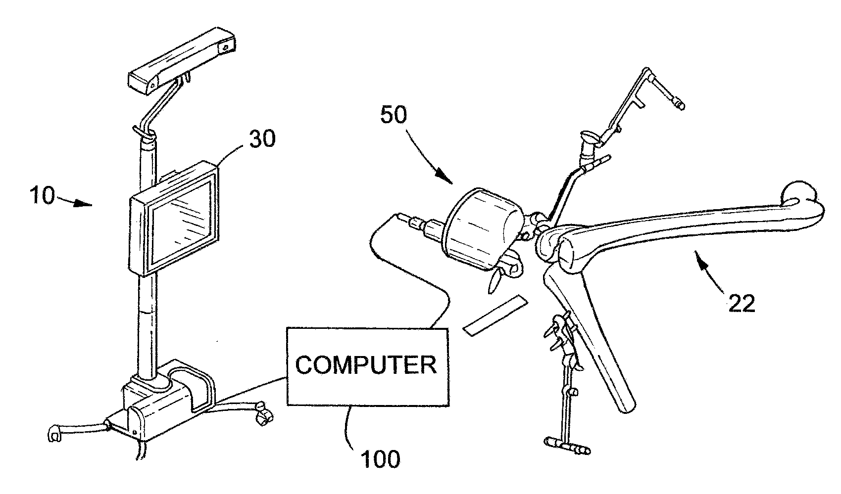
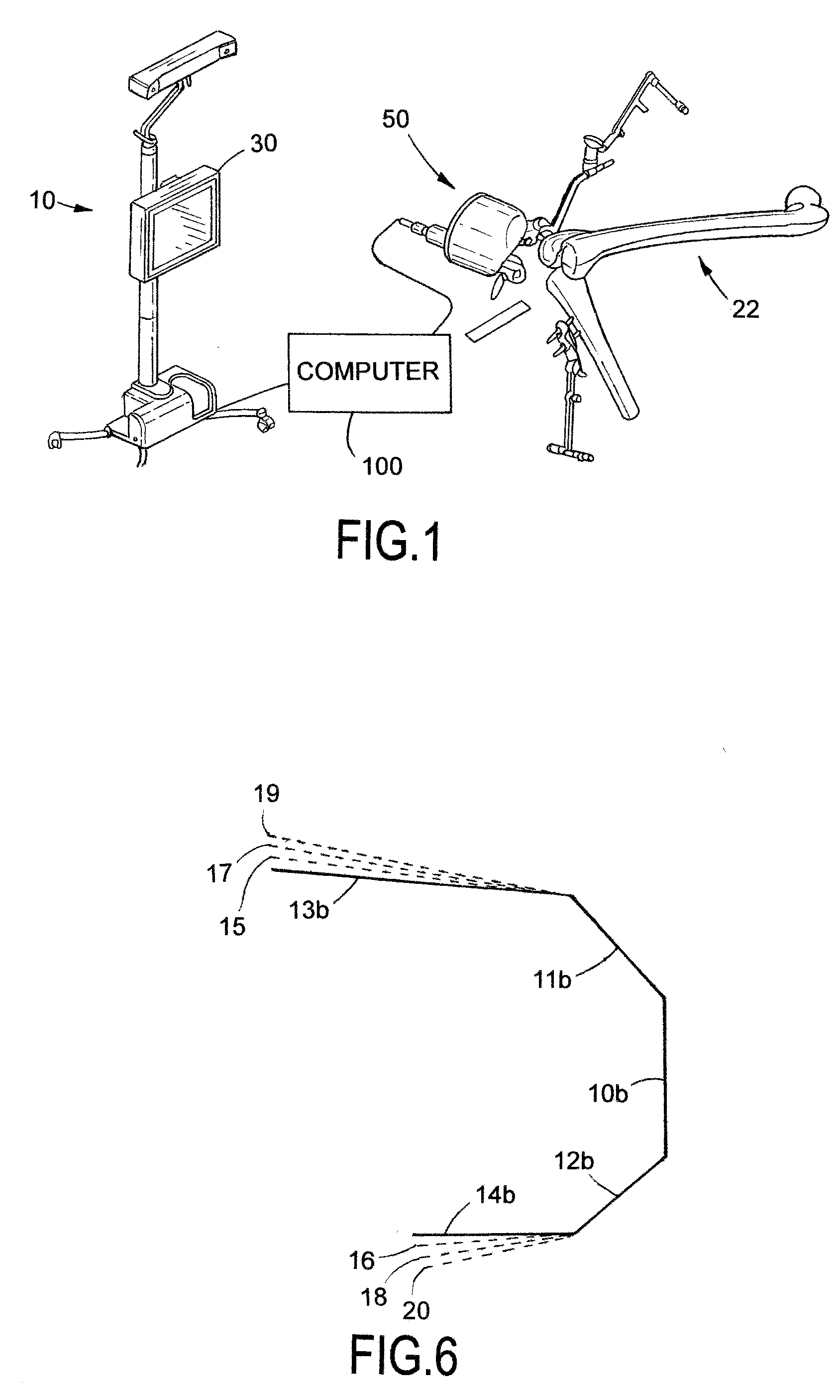
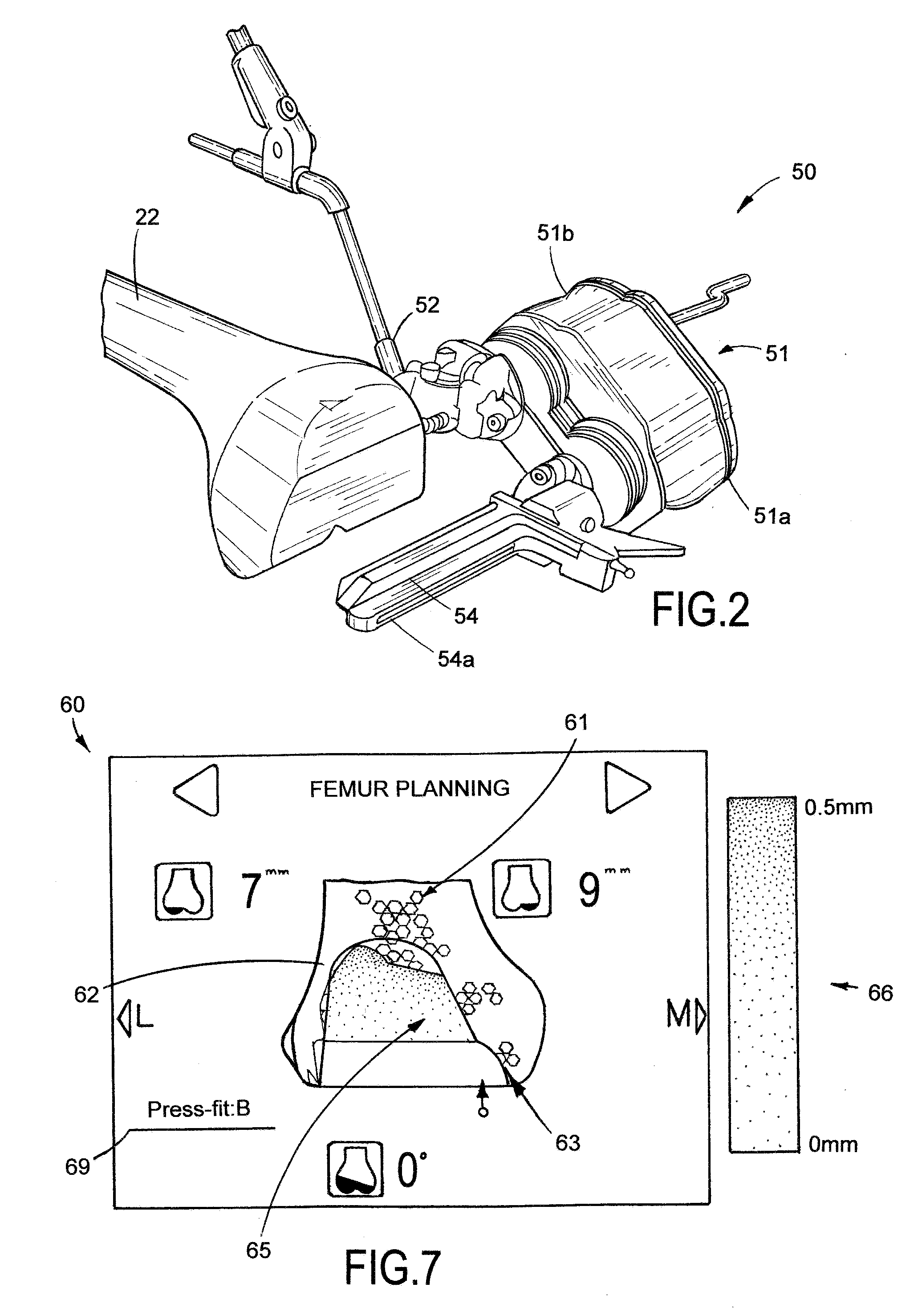
BACKGROUND OF THE INVENTION[0001]The present invention relates to an improved system and method for bone preparation for an implant. In particular, the present invention relates to a computer assisted surgical system and method for resecting bone to receive an orthopedic implant for press-fit applications.[0002]Arthroplasty or joint replacement surgical procedures require accurate bone preparation for the implantation of prosthetic components i.e., implants. A precise fit between the implant and resected bone is desired for good fixation in both cementless and cemented applications in order to prevent loosening of the implant over time. Furthermore, an interference fit or “press-fit” is often desired to ensure good fixation of the implant to the bone, and for osteointegration of cementless devices. The amount of interference fit to apply, however, is difficult to ascertain and often determined by empirical methods with the benefit of intra-operative evaluations of the patient's bone...

Claims


Application Information

Patent Timeline
IPC IPC(8): A61B17/17A61B17/88A61B19/00
CPCA61B17/155A61B34/30A61B34/10A61B2034/105A61B2034/107A61B90/37A61B17/17A61F2/46A61F2/4657A61F2002/4633
Inventor CHEAL, EDWARD J.CIPOLLETTI, GEORGELASALLE, DAVID L.KNOBLOCH, CARLPLASKOS, CHRISTOPHER
Owner OMNILIFE SCI INC
Why Eureka
Try Eureka