Determination of media characteristics in fill-level measuring

a technology of fill-level measurement and media characteristics, applied in the direction of level indicators by physical variable measurement, liquid/fluent solid measurement, engine lubrication, etc., can solve the problem that radar fill-level measuring results are often inaccura

Active Publication Date: 2012-12-27
VEGA GRIESHABER GMBH & CO
View PDF8 Cites 12 Cited by
  • Summary
  • Abstract
  • Description
  • Claims
  • Application Information

AI Technical Summary

Problems solved by technology

It has been found that fill-level measuring results that are based on radar fill-level sensors are often not accurate.

Method used


Image

  • Determination of media characteristics in fill-level measuring
  • Determination of media characteristics in fill-level measuring
  • Determination of media characteristics in fill-level measuring

Examples


Embodiment Construction

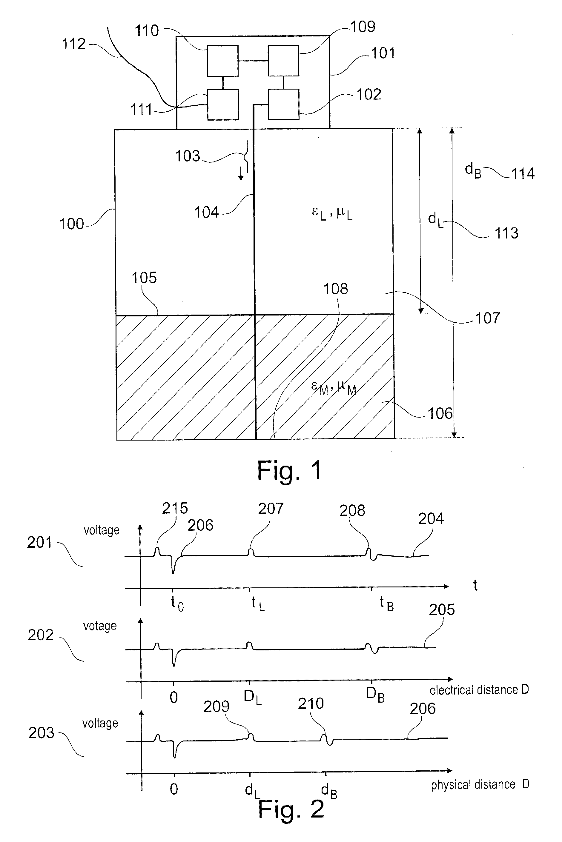
[0049]If in the following description of the figures in various figures the same reference characters are used, these describe identical or similar elements. However, identical or similar elements can also be designated by different reference characters.

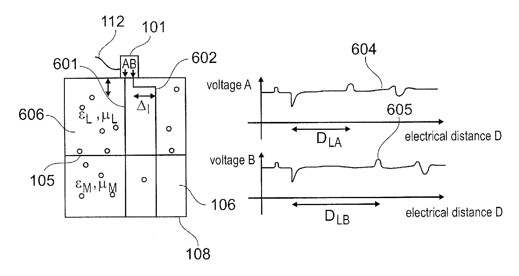
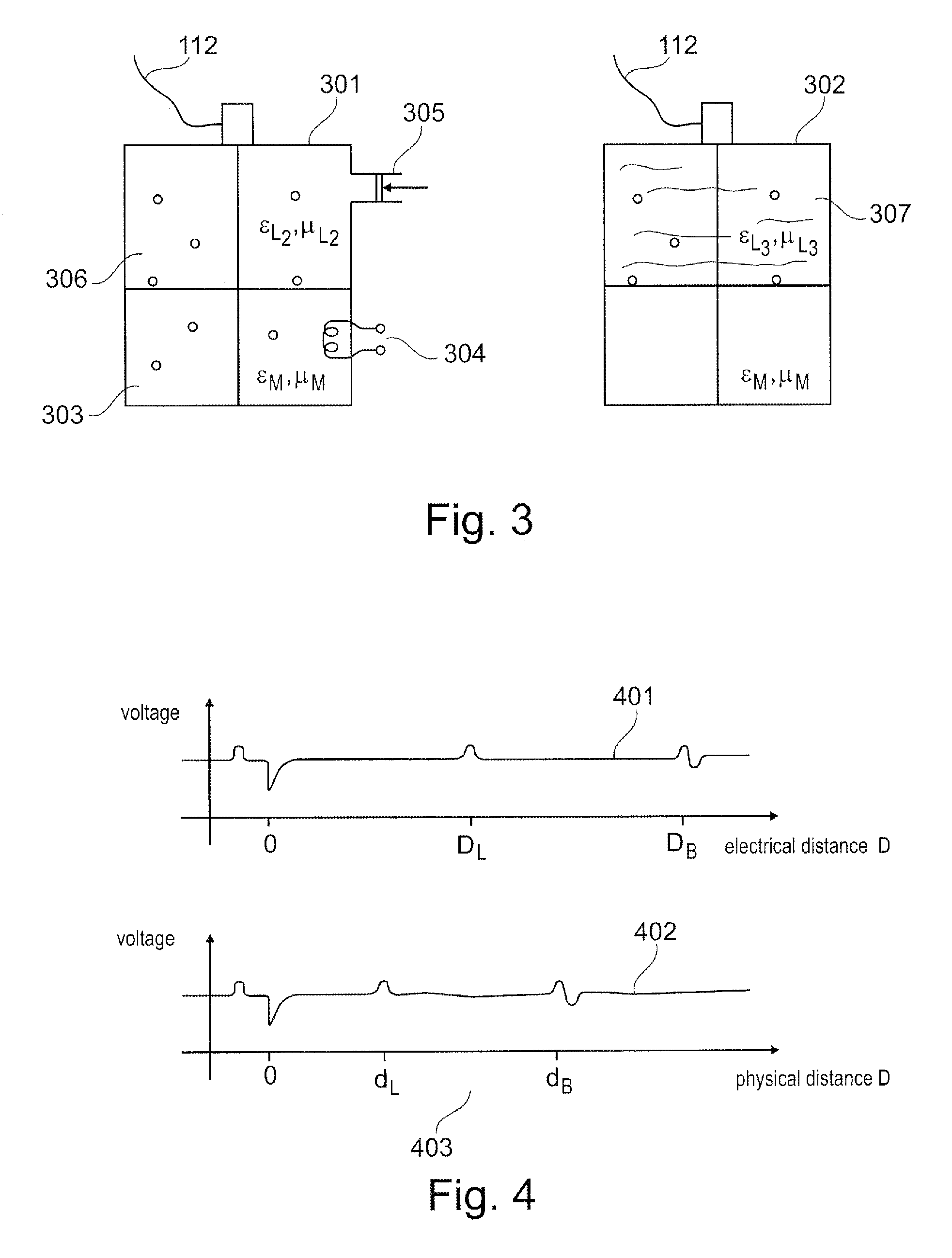
[0050]All the methods share a common feature in that the signals used for measuring, on their way from the fill-level measuring device to the feed material surface and / or separating layer surface, are normally in the field of influence of a further medium that hereinafter is referred to as the overlay or covering medium.

[0051]An overlay medium is a medium or a mixture of different media that is situated between the emitting position of the measuring signal of the fill-level measuring device (for example the antenna of the fill-level measuring device) and the surface of the medium to be measured, or between the emitting position of the measuring signal of the fill-level measuring device (for example the antenna of the fill-level measu...


PUM


Abstract

For calculating the fill level in a container two echo curves are acquired that image the reflection conditions along two different measuring paths. On their way to the filling material surface or the separating layer surface the corresponding measuring signals cover different electrical distances. From the two echo curves a characteristic value can be calculated that reflects a physical characteristic of the covering medium. From this, the fill level can then be determined with increased accuracy.

Description

REFERENCE TO RELATED APPLICATIONS[0001]This application claims the benefit of the filing date of PCT Patent Application Serial No. PCT / EP2010 / 069984 filed 16 Dec. 2010 and U.S. Provisional Patent Application Ser. No. 61 / 423,792 filed 16 Dec. 2010, the disclosure of both applications is hereby incorporated by reference.TECHNICAL FIELD[0002]The invention relates to the determination of media characteristics in measuring fill levels of all kinds. In particular, the invention relates to a fill-level measuring device that operates according to a transit time method, to a fill-level measuring arrangement, to its use, and to a method for fill-level measuring.BACKGROUND INFORMATION[0003]In fill level sensors operating according to the FMCW method or pulse-transit time method electromagnetic or acoustic waves are emitted in the direction of a feed material surface (in the following also referred to as “filling material surface”). Subsequently a sensor records the echo signals reflected by th...

Claims


Application Information

Patent Timeline
Patent Type & Authority Applications(United States)
IPC IPC(8): G01F23/296G01F23/284
CPCG01F23/2962G01F23/284
Inventor WELLE, ROLANDGRIESSBAUM, KARL
Owner VEGA GRIESHABER GMBH & CO
Why Eureka
Try Eureka