Tank rubber cushion

a technology of rubber cushion and tank, which is applied in the direction of shock absorbers, mechanical devices, transportation and packaging, etc., can solve the problems of restricted fuel movement in the fuel tank due to displacement, and achieve the effect of effectively exerting an attenuation effect against the transmission of fuel flow nois

Active Publication Date: 2012-12-27
SUMITOMO RIKO CO LTD +1
View PDF10 Cites 11 Cited by
  • Summary
  • Abstract
  • Description
  • Claims
  • Application Information

AI Technical Summary

Benefits of technology

[0024]According to the seventh mode, biased stress is prevented from acting on the transaxial vibration-damping rubber portion of one of the divided rubber cylinders, which achieves high durability of either of the divided rubber cylinders.
[0025]According to the present invention, a high spring constant is realized in the axial direction by the compression spring component of the axial vibration-damping rubber portion placed between the opposing surfaces of the flanges to effectively obtain a load bearing capacity and a displacement limiting action of the fuel tank and the like. Meanwhile, in the transaxial direction, a low spring constant is realized through the shearing spring component of the transaxial vibration-damping rubber portion by providing the concave / convex portion to the transaxial vibration-damping rubber portion interposed between the inner axial member and support portion, thus effectively exerting an attenuation effect against transmission of fuel flow noise.

Problems solved by technology

Moreover, movement of fuel in the fuel tank due to displacement thereof is restricted, which stably supplies fuel to the engine.

Method used


Image

  • Tank rubber cushion
  • Tank rubber cushion
  • Tank rubber cushion

Examples


Embodiment Construction

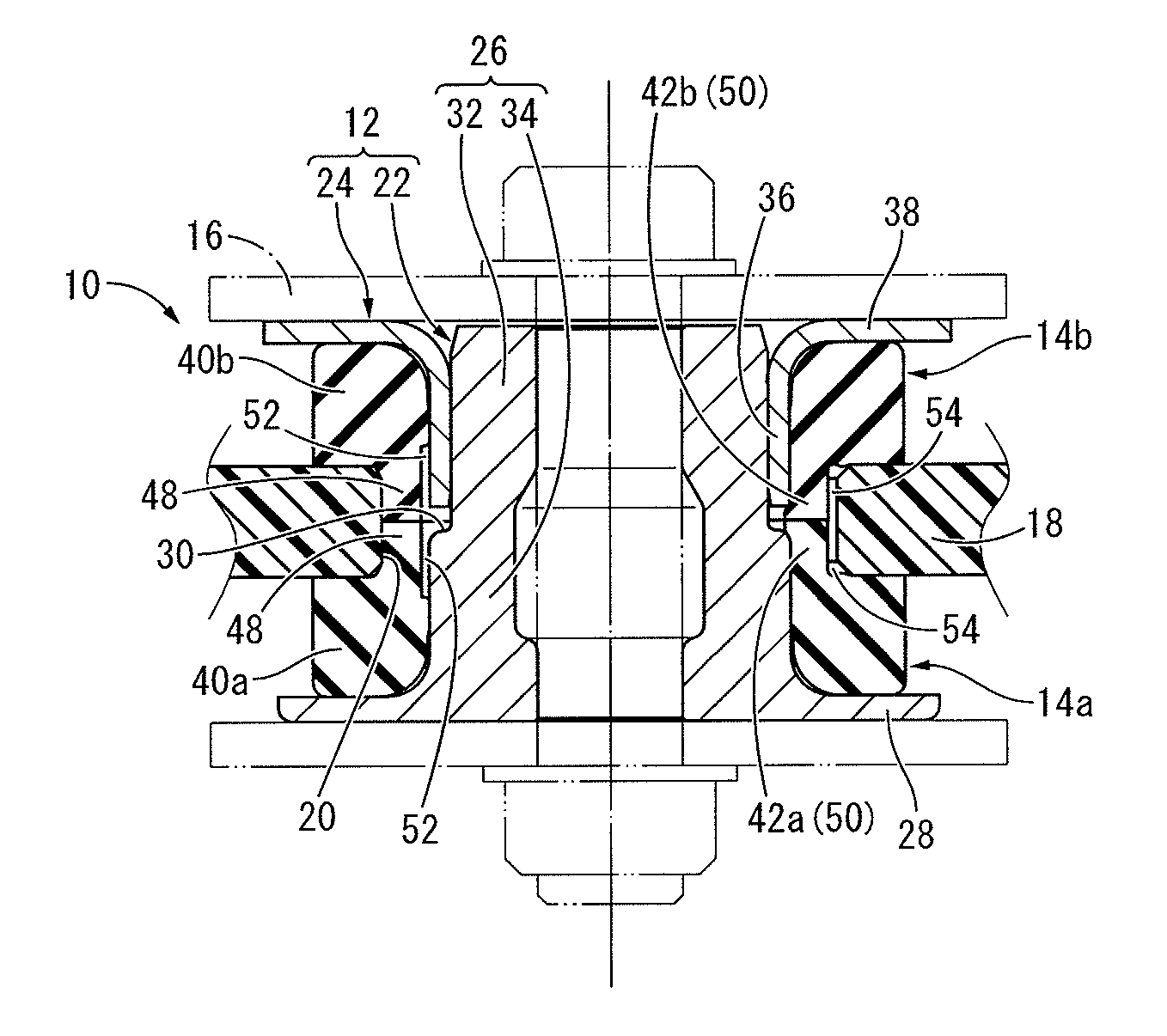
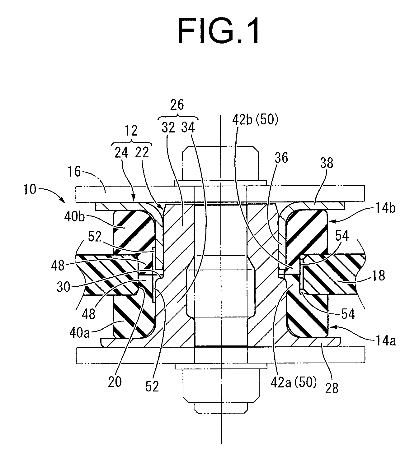
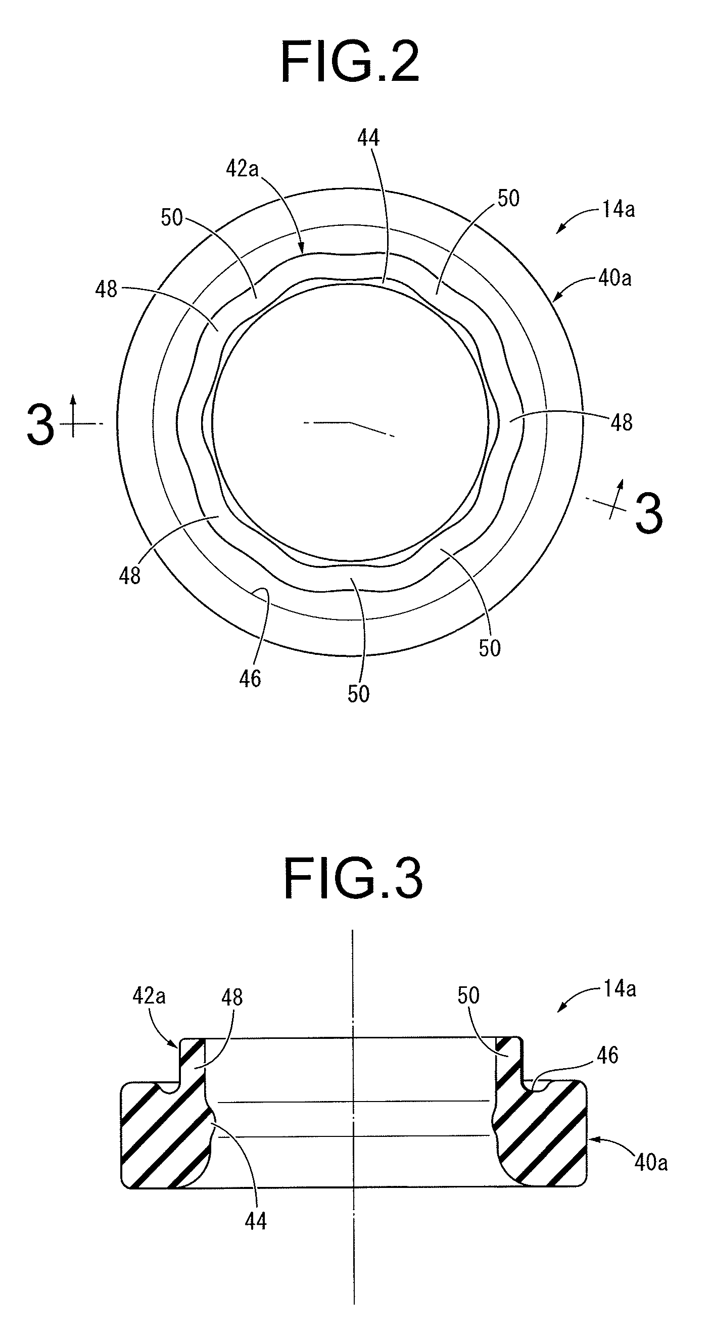
[0035]FIG. 1 shows a tank rubber cushion 10 to be used for supporting a vehicular fuel tank as one embodiment of the tank rubber cushion with a structure according to the present invention. The tank rubber cushion 10 has a structure where two divided rubber cylinders 14a and 14b are attached to an inner axial member 12. Then, the inner axial member 12 is directly fixed to a mounting piece 16 on the side of the vehicle body, and at the same time, inserted through a mounting hole 20 of a support portion 18 provided on the side of the fuel tank so that it is indirectly attached to the fuel tank via the two divided rubber cylinders 14a and 14b, thus allowing the fuel tank, not shown, to be supported by the vehicle body in a vibration-damping way. The fuel tank is supported via a plurality of tank rubber cushions 10 at multiple locations by the vehicle body. In the following descriptions, the vertical direction generally means an approximate up and down direction under installation of th...


PUM

PropertyMeasurementUnit
vibration-dampingaaaaaaaaaa
diameteraaaaaaaaaa
thicknessaaaaaaaaaa

Abstract

A tank rubber cushion for providing a vibration-damping support of a fuel tank against a vehicle body, including two divided rubber cylinders inserted onto an inner axial member having flanges at both axial ends and to be inserted through a mounting hole formed in a support portion of the fuel tank. Each of the divided rubber cylinders is provided with an axial vibration-damping rubber portion arranged between opposing surfaces of the flange of the inner axial member and the support portion in an axial direction, and a transaxial vibration-damping rubber portion arranged between opposing surfaces of the inner axial member and the support portion in a transaxial direction. The transaxial vibration-damping rubber portion includes a concave/convex portion wherein a diameter varies in a circumferential direction so that an assembly can be made with a gap between the inner axial member and the support portion.

Description

INCORPORATED BY REFERENCE[0001]The disclosure of Japanese Patent Application No. 2010-243546 filed on Oct. 29, 2010 including the specification, drawings and abstract is incorporated herein by reference in its entirety. This is a Continuation of International Application No. PCT / JP2011 / 005705 filed on Oct. 12, 2011.BACKGROUND OF THE INVENTION[0002]1. Field of the Invention[0003]The present invention relates to a tank rubber cushion for providing a vibration-damping support of a fuel tank against a vehicular body.[0004]2. Description of the Related Art[0005]Tank rubber cushions have conventionally been used in order to let a fuel tank be supported by the vehicular body. One such example is the one described in U.S. Publication No. US 2009 / 0077785.[0006]Meanwhile, a tank rubber cushion is required to have a vibration-damping performance so as to achieve stable supplies of fuel into the tank and reduce transmission of vibration to the vehicular body caused by a displacement of the fuel...

Claims


Application Information

Patent Timeline
Patent Type & Authority Applications(United States)
IPC IPC(8): F16F15/08
CPCB60K15/067F16F15/08F16F1/3732F16F1/387B60K15/063F16F1/36F16F1/38
Inventor KAWACHI, YUYAMAEHASHI, HIDEKIFURUSAWA, TAKASHIKOBAYASHI, JUN
Owner SUMITOMO RIKO CO LTD
Why Eureka
Try Eureka