

Multi-fiber, fiber optic cable assemblies providing constrained optical fibers within an optical fiber sub-unit, and related fiber optic components, cables, and methods
a fiber optic cable and fiber optic sub-unit technology, applied in the field of multi-fiber, fiber optic cables, and related fiber optic components and assemblies, can solve the problems of fiber distribution cables in fiber optic communications networks, transmission errors, and optical fibers in multi-fiber distribution cables can be damaged, so as to reduce the risk of damage, reduce the complexity of fiber optic cable assembly preparation, and reduce the effect of optical skew
- Summary
- Abstract
- Description
- Claims
- Application Information
AI Technical Summary
Benefits of technology
Problems solved by technology
Method used
Image

Examples
Embodiment Construction
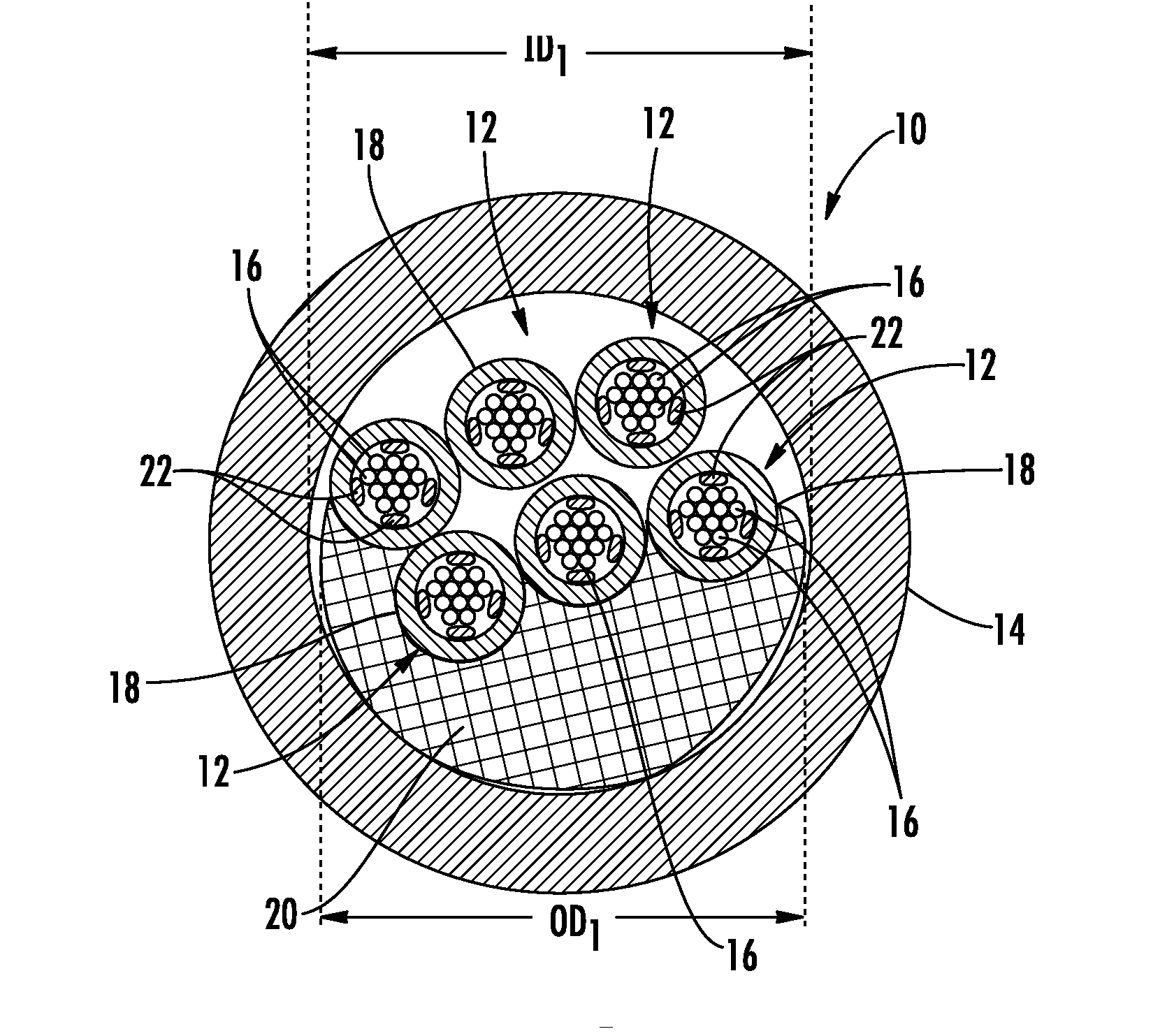
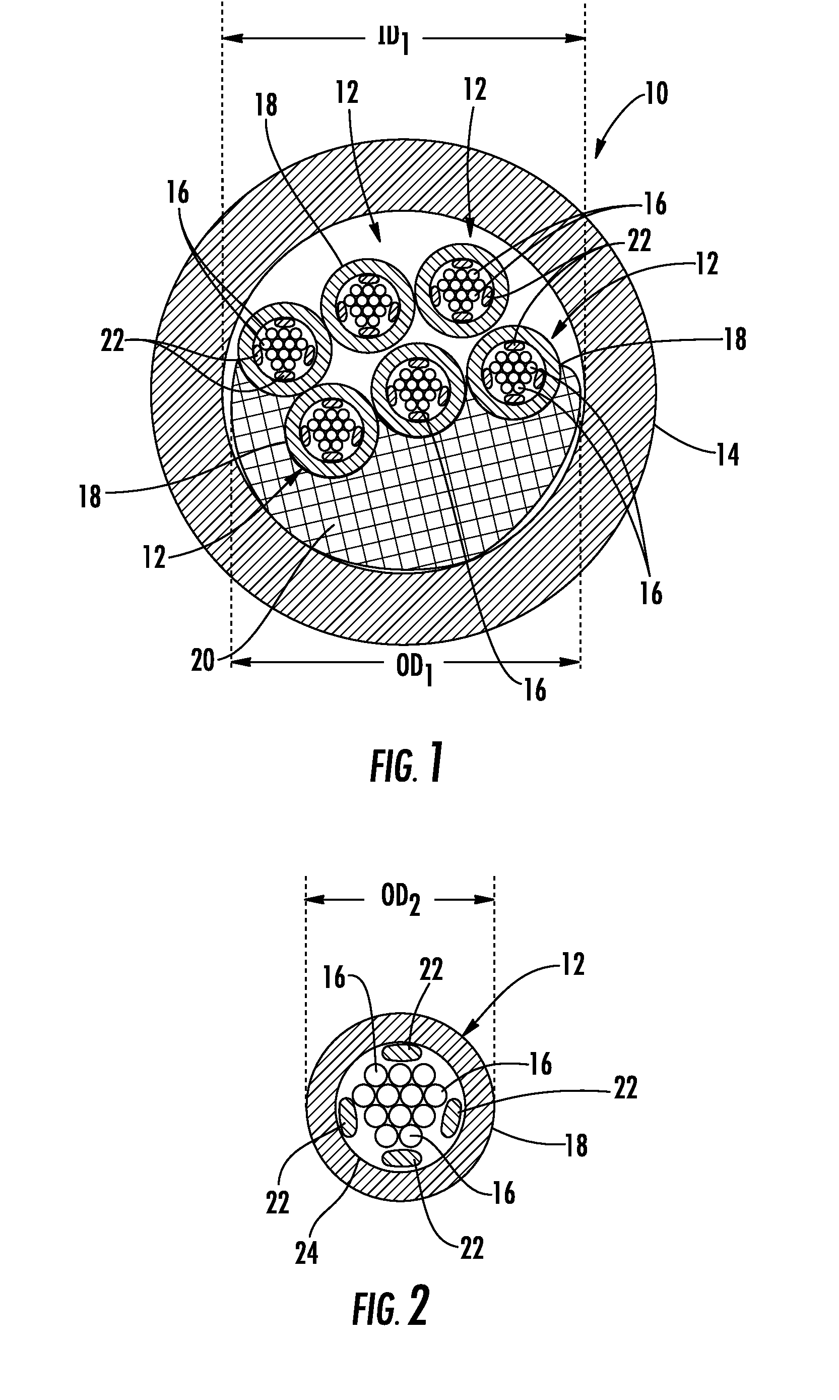
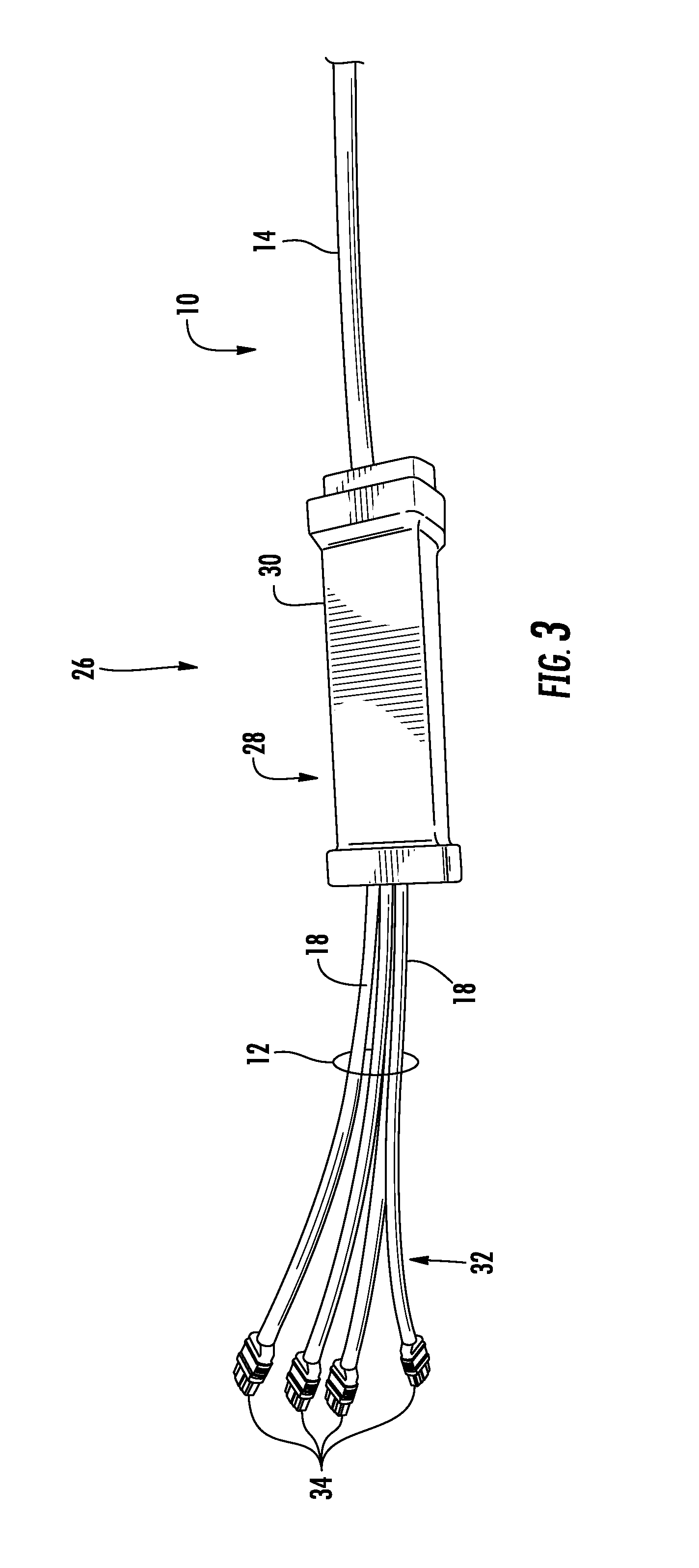
[0006]Embodiments disclosed in the detailed description include multi-fiber, fiber optic cables providing constrained optical fibers within an optical fiber sub-unit disposed in a cable jacket. Related fiber optic components and fiber optic assemblies are also disclosed. In one embodiment, one or more optical fiber sub-units can be provided that each comprises a plurality of optical fibers disposed adjacent one or more sub-unit strength members within a sub-unit jacket. Movement of optical fibers within a sub-unit jacket is constrained by an interior wall of the sub-unit jacket and / or the sub-unit strength members disposed in the sub-unit jacket. In this manner as a non-limiting example, optical fibers disposed in an optical fiber sub-unit can be held together as a unit within the optical fiber sub-unit. By providing the optical fibers constrained as a unit in optical fiber sub-units, the optical fiber sub-units may be constrained in a furcation assembly without having to expose the...
PUM
| Property | Measurement | Unit |
|---|---|---|
| outer diameter | aaaaa | aaaaa |
| inner diameter ID1 | aaaaa | aaaaa |
| outer diameter OD2 | aaaaa | aaaaa |
Abstract
Description
Claims
Application Information