
Method for controlling drive test logged measurement, drive test system and user equipment

a drive test and logging technology, applied in the field of radio cellular communication system, can solve the problems of huge waste of manpower, material resources and time, slow operation of the ue, etc., and achieve the effect of saving memory space and managing storage space much more effectively

Active Publication Date: 2012-12-27
ZTE CORP
View PDF2 Cites 24 Cited by
  • Summary
  • Abstract
  • Description
  • Claims
  • Application Information

AI Technical Summary

Benefits of technology

[0004]The technical problem to be solved by the disclosure is to provide a method for controlling DT logged measurement, a DT system and a UE, to effectively control and manage the logged measurement.
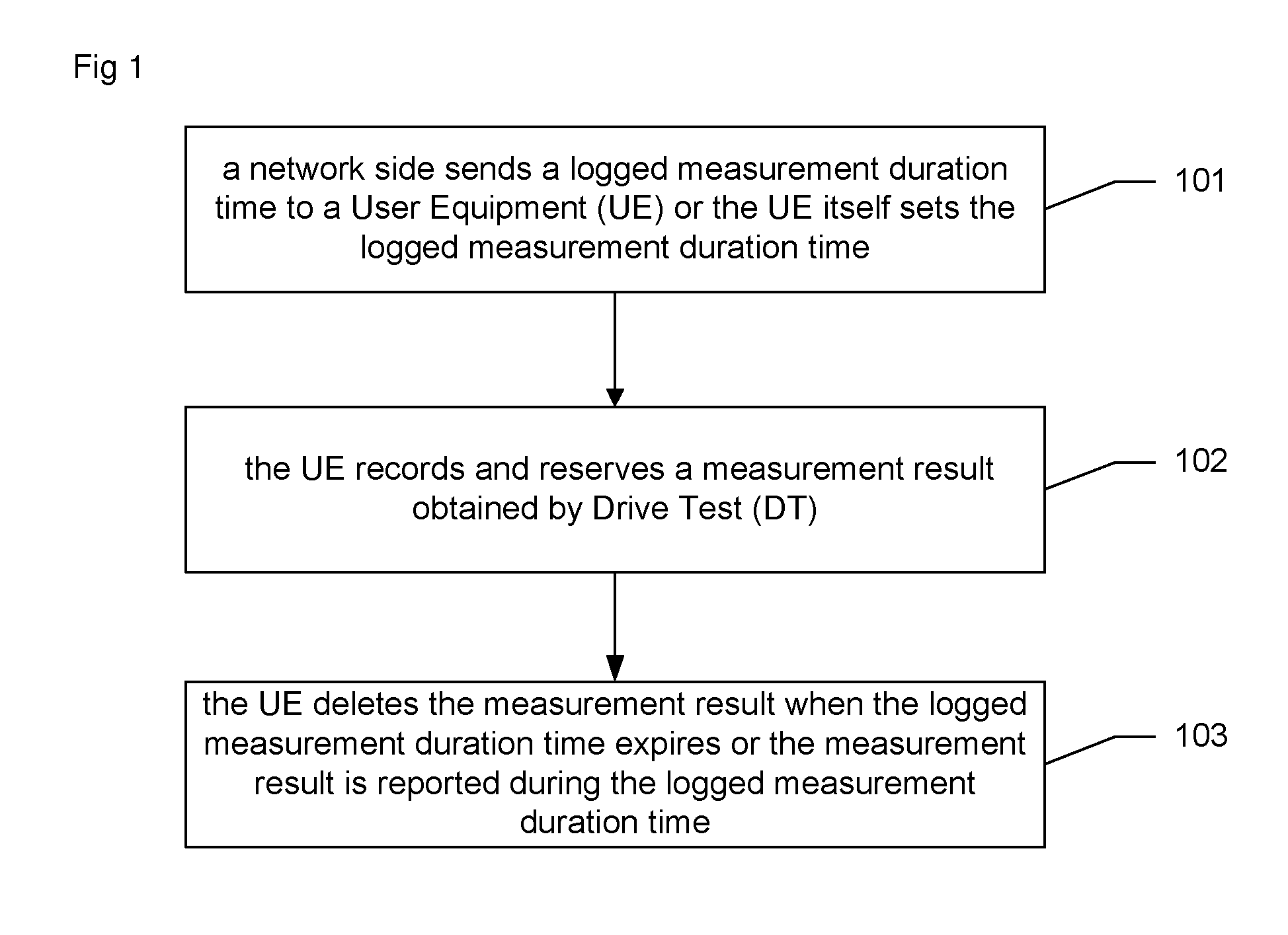
[0030]In the method for controlling DT logged measurement, the DT system and the UE, the network side sends logged measurement duration time to the UE or the UE sets logged measurement duration time itself, when the logged measurement duration time expires or the measurement result is reported during the logged measurement duration time, the UE deletes the measurement result, thereby controlling the length of the duration time of the reservation of the measurement result in the UE when the UE is not triggered to report the measurement result in a long time; therefore, the UE reports the measurement result and manages the storage space much more effectively, thus memory space is saved.

Problems solved by technology

The DT can carry out fairly well the test and evaluation of the mobile network, however, with the defect of huge waste in manpower, material resources, and time.
For the mode of Logged DT, after the UE receives a DT measurement configuration sent by the network side, wherein the configuration has a duration time, and during the configuration duration time, the UE can perform DT measurement; when the configuration duration time expires, the UE stops logging; after the logging is stopped, if the UE continues to keep the unreported measurement result, a lot of memory of the UE will be occupied, resulting in slow operation of the UE.

Method used


Image

  • Method for controlling drive test logged measurement, drive test system and user equipment
  • Method for controlling drive test logged measurement, drive test system and user equipment
  • Method for controlling drive test logged measurement, drive test system and user equipment

Examples


embodiment 1

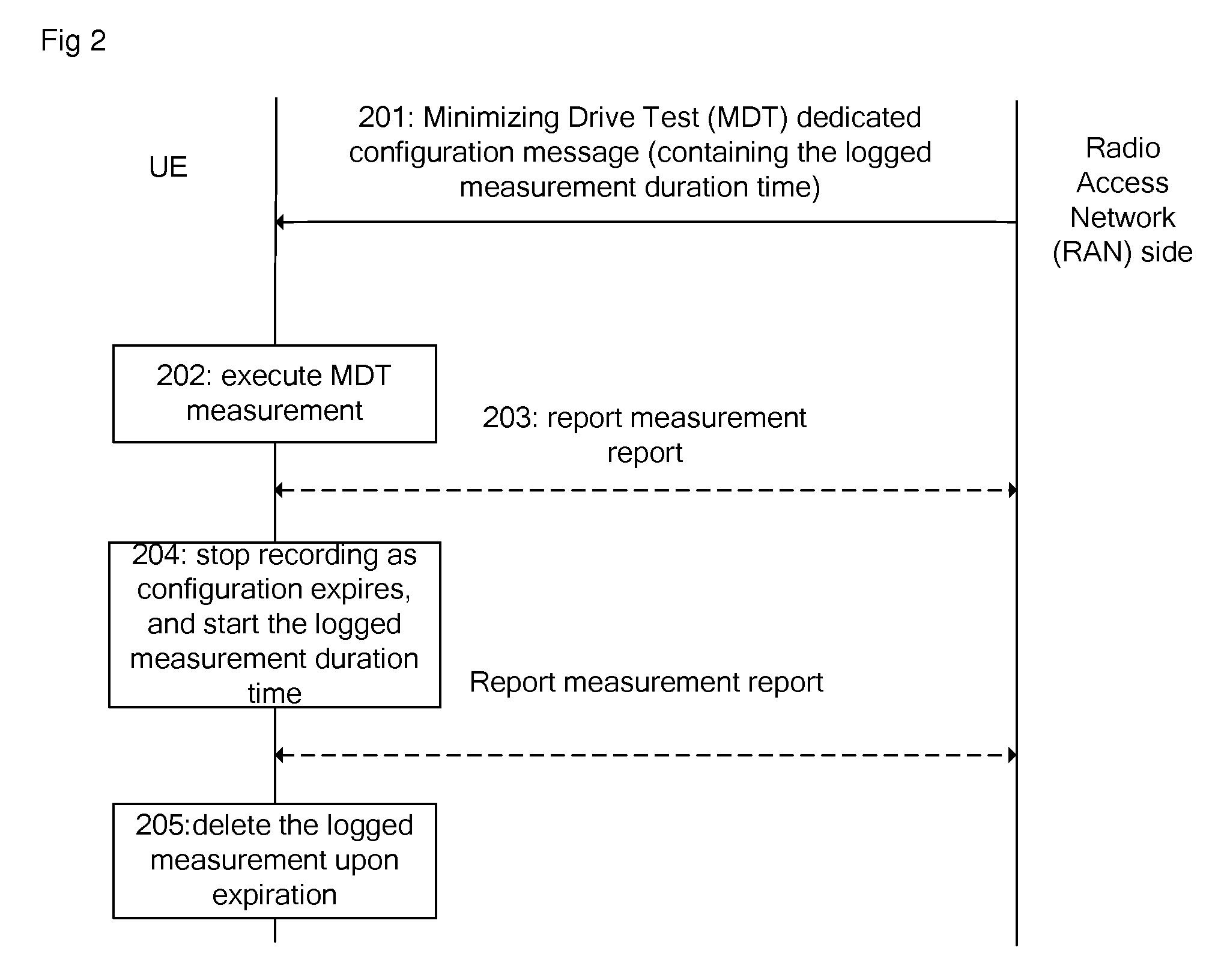
The Measurement Control Process of Sending the Logged Measurement Duration Time Through a Dedicated Message for DT Configuration (See FIG. 2)

[0047]Step 201: when the UE performs RRC connection establishment in a serving cell, the network side sends DT configuration information of delayed report (Logged MDT measurement configuration) through a dedicated DT configuration message (for example, MDTMeasConfiguration), wherein the DT configuration information includes measurement configuration content (for example, measurement frequency, cell, event of measurement triggering record, and so on), configuration duration time and logged measurement duration time (for example, LogKeep Timer).

[0048]Step 202: the measurement configuration takes effect after the UE receives the DT configuration information; at this moment, the configuration duration time starts. After the UE enters IDLE state, the UE performs, records, and stores the related measurement when the measurement triggering conditions ...

embodiment 2

The DT Measurement Control Process of Sending the Logged Measurement Duration Time Through an Existing Configuration Message (see FIG. 3)

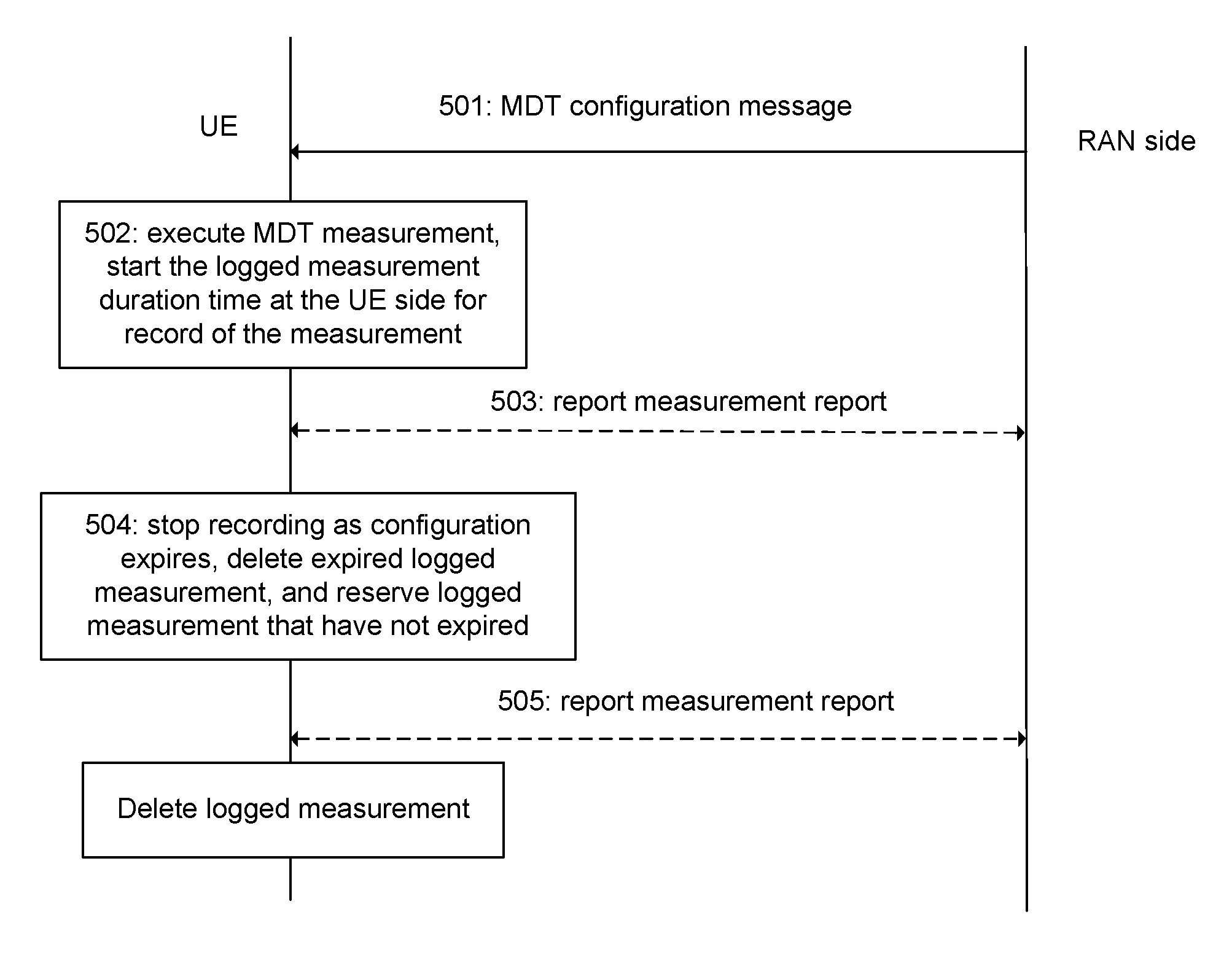
[0053]Step 301: after the UE performs RRC connection establishment in a serving cell and enters connection state, the network side sends measurement configuration through a dedicated DT configuration message, and configures the logged measurement duration time of DT (for example, LogKeep Timer) in the RRC connection release message (RRCConnectionRelease) for the UE to release RRC connection and enter IDLE state, so as to send the logged measurement duration time to the UE.

[0054]Step 302: the measurement configuration takes effect after the UE receives the measurement configuration of DT. At this moment, the configuration duration time starts. After the UE enters IDLE state, the UE performs, records, and stores the related measurement, and starts the logged measurement duration time (for example, LogKeep timer) when a first measurement is recorded w...

embodiment 3

The DT Measurement Control Process Performed by Setting the Logged Measurement Duration Time Through a Broadcast Message (see FIG. 4)

[0058]Step 401: when the UE performs RRC connection establishment in a serving cell, the network side sends through a dedicated DT configuration message (for example, MDTMeasConfiguration), DT measurement configuration information of delayed report (Logged MDT measurement configuration) wherein the DT configuration information includes measurement configuration content (for example, measurement frequency, cell, conditions of event triggering record) and the configuration duration time.

[0059]Step 402: the measurement configuration takes effect after the UE receives the DT configuration information; at this moment, the configuration duration time starts. After the UE enters IDLE state, the UE performs, records, and stores the related measurement when the measurement triggering conditions of DT are met (for example, periodic pilot frequency measurement, o...


PUM


Abstract

The disclosure discloses a method for controlling Drive Test (DT) logged measurement, a DT system and User Equipment (UE). The method comprises the steps of: sending a logged measurement duration time to a UE by a network side or setting the logged measurement duration time by the UE itself; recording and reserving, by the UE, a measurement result obtained by DT; deleting the measurement result by the UE when the logged measurement duration time expires or the measurement result is reported during the logged measurement duration time. The disclosure makes the UE more efficient in reporting the measurement result and managing the storage space, thus saving memory space.

Description

FIELD OF THE INVENTION[0001]The disclosure relates to a radio cellular communication system, more particularly, to a method for controlling Drive Test (DT) logged measurement, a DT system and User Equipment (UE) in a radio mobile communication system.BACKGROUND OF THE INVENTION[0002]A Long Term Evolution (LTE) network consists of an Evolved UMTS (Universal Mobile Telecommunications System) Terrestrial Radio Access Network (E-UTRAN) Evolved Node B (eNB) and Evolved Packet Cores (EPC), wherein the network fabric is flat. The EUTRAN includes a set of eNBs connected with the EPC via S1 interfaces; the eNBs can be interconnected via X2, wherein the S1 and the X2 are logic interfaces. One EPC can manage one or more eNBs; one eNB also can be controlled by a plurality of EPCs; and one eNB can manage one or more cells. The EPC consists of a Mobility Management Entity (MME), a Serving Gateway (SGW), and a Packet Data Network Gateway (PGW). A UMTS consists of a UMTS Terrestrial Radio Access Ne...

Claims


Application Information

Patent Timeline
IPC IPC(8): H04W24/10
CPCH04W24/10H04W24/06
Inventor REN, LONGTAOHAN, LIFENGGAO, YIN
Owner ZTE CORP
Learn More