Fuel Hose Assembly for In-Flight Fuelling of Aircraft

Pending Publication Date: 2021-11-25
BRULIC LTD
View PDF0 Cites 0 Cited by
  • Summary
  • Abstract
  • Description
  • Claims
  • Application Information

AI Technical Summary

Benefits of technology

The invention is a fuel hose assembly that can handle high pressure and flow rates while being relatively compact and stable. It consists of two parts: rigid parts and flexible inner tube. When the assembly is compressed, the rigid parts form a continuous line along the flexible inner tube, providing continuous coverage and preventing bulging of the inner tube that could lead to rupture. This allows for high-pressure levels without excessive expansion of the inner tube. Additionally, the rigid parts also enhance the stability of the assembly in the air, reducing the required pilot skill and training. When the assembly is relaxed, it can be bent and conveniently reeled on a hose drum unit in an aircraft. Overall, this fuel hose assembly is highly suitable for use in commercial and military inflight fuelling operations.

Problems solved by technology

Significant radial expansion of the flexible inner tube is undesirable because it could lead to rupture (catastrophic structural failure) of the inner tube.

Method used


Image

  • Fuel Hose Assembly for In-Flight Fuelling of Aircraft
  • Fuel Hose Assembly for In-Flight Fuelling of Aircraft
  • Fuel Hose Assembly for In-Flight Fuelling of Aircraft

Examples


Embodiment Construction

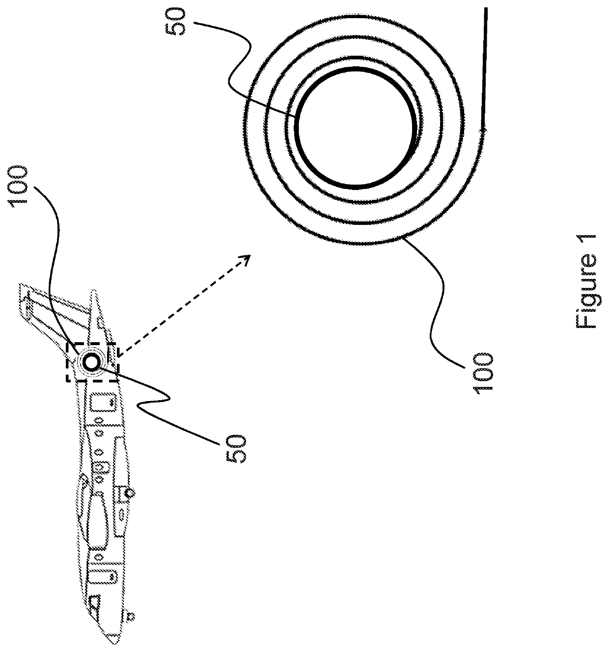
[0042]FIG. 1 shows a fuel tanker aircraft comprising a fuel hose assembly 100 which is coiled on a motorised hose drum unit 50 and is provided with a fuel supply carried by the tanker aircraft.

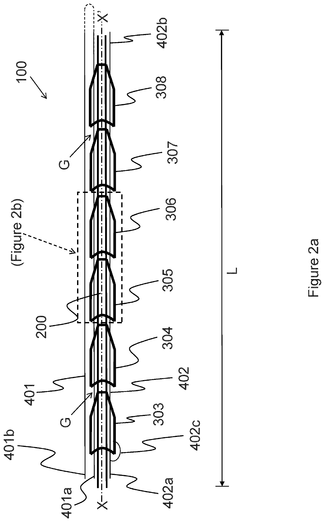
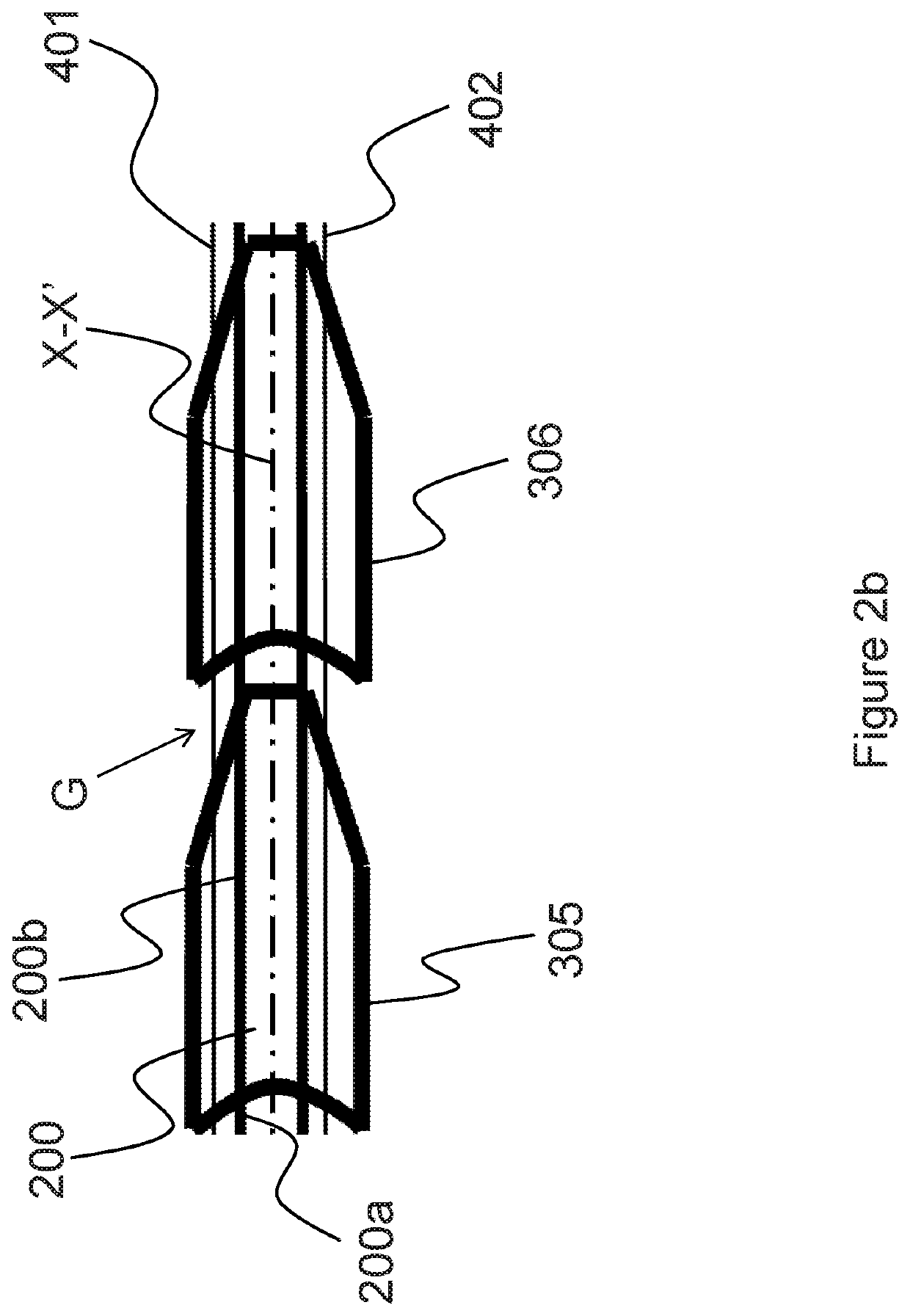
[0043]FIG. 2a shows an exemplary portion of the fuel hose assembly 100, the portion having a length L and a longitudinal axis X-X′. The fuel hose assembly 100 comprises an elongate, tubular core 200, a plurality of rigid segments 301-311, and first and second control cords 401, 402 and associate cords (only one of the associate cords 402c being shown in FIG. 2a). The rigid segments 301-311 are separated (spaced apart) by gaps G. It will be understood that only some of the rigid segments 303-308 of the fuel hose assembly 100 are visible in FIG. 2a because the figure shows only a portion of the fuel hose assembly 100. For ease of understanding of the following description, FIG. 2b shows an enlarged detail of part of the fuel hose assembly 100 of FIG. 2a.

[0044]The tubular core 200 comprises an i...


PUM


Abstract

A fuel hose assembly for inflight fuelling of aircraft comprises: a flexible inner tube for conveying fuel under pressure; an outer cover comprising a plurality of rigid parts; and an actuator configured to move the rigid parts lengthwise along the flexible inner tube. The rigid parts are movable by the actuator to provide continuous lengthwise cover over the flexible inner tube, so as to be able to resist radial expansion of the flexible inner tube when the flexible inner tube is pressurised. The rigid parts are further movable by the actuator to uncover lengthwise portions of the flexible inner tube between the rigid parts, so as to allow bending of the flexible inner tube when the flexible inner tube is unpressurised.

Description

BACKGROUND OF THE INVENTION[0001]The present invention relates to a fuel hose assembly for in-flight (re)fuelling of aircraft.[0002]In-flight refuelling (IFR) involves the transfer of fuel from one aircraft (the “tanker”) to another aircraft (the “receiver”) during flight. IFR (also known as aerial refuelling or air-to-air refuelling) has become a well-established methodology used to extend the range or loiter time (or increase take-off payload) of military aircraft. Typically the tanker is based on an airliner which has been specially redesigned or converted for refuelling operations, while the receiver is usually a fighter aircraft, or possibly a bomber or reconnaissance aircraft.[0003]Today there are two different IFR methods in widespread use: flying boom and probe-and-drogue.[0004]The flying boom is attached at the rear of the tanker and comprises a rigid, telescopic and articulated tube having a nozzle at one end. The boom includes flight control surfaces which can be moved to...

Claims


Application Information

Patent Timeline
IPC IPC(8): B64D39/04F16L11/12F16L11/18
CPCB64D39/04F16L11/18F16L11/12B67D7/0401
Inventor PITMAN, JAMES
Owner BRULIC LTD
Why Eureka
Try Eureka