
Connector

Inactive Publication Date: 2008-08-14
SUMITOMO WIRING SYST LTD
View PDF8 Cites 4 Cited by
  • Summary
  • Abstract
  • Description
  • Claims
  • Application Information

AI Technical Summary

Benefits of technology

[0008]The invention relates to a connector assembly that includes first and second connectors. The first connector includes a receptacle and is mountable to an electric or electronic device, such as a circuit board. The second connector is fittable into the receptacle. The receptacle of the first connector has a lower wall that faces the electric or electronic device. The lower wall of the receptacle of the first connector is formed with at least one reinforcing rib that extends substantially along a connecting direction of the two connectors for reinforcing the wall. A receiving groove is formed in the second connector for receiving the reinforcing rib upon connecting the two connectors. At least one engageable portion projects from t

Problems solved by technology

However, the upper wall cannot be thinned very much even if reinforcing ribs are formed on the upper.

Method used


Image

  • Connector
  • Connector
  • Connector

Examples


first embodiment

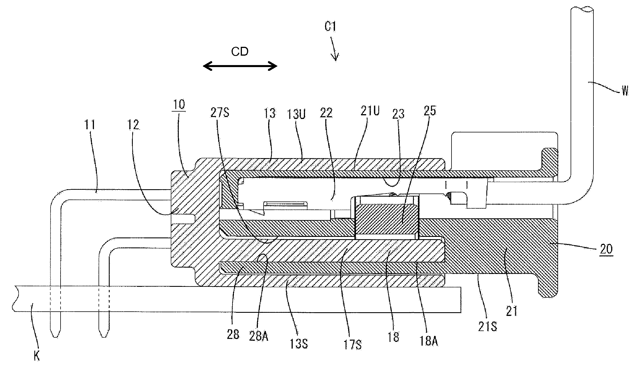
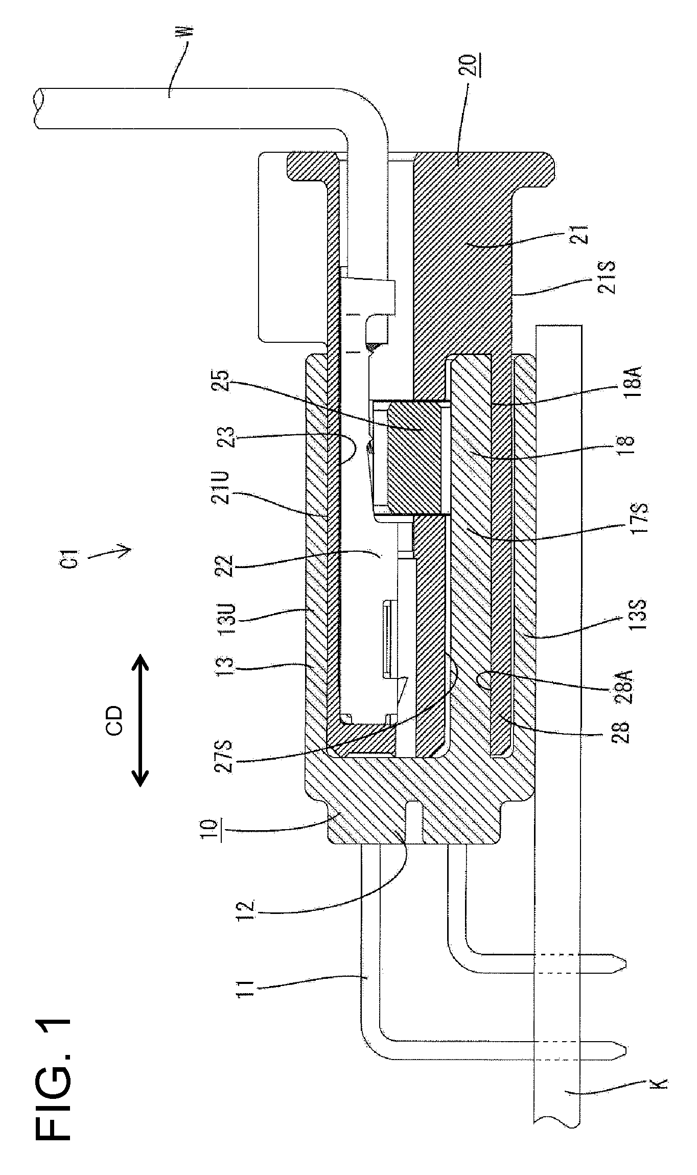
[0023]A board connector assembly in accordance with the invention is illustrated in FIGS. 1 to 4. The connector assembly is identified generally by C1 in FIG. 1 and includes a male connector 10 that is mountable on a circuit board K and a female connector 20 connectable along a connecting direction CD with the male connector 10. In the following description, ends of the connectors 10, 20 that are to be connected are referred to as front ends and reference is made to FIG. 1 concerning vertical direction.

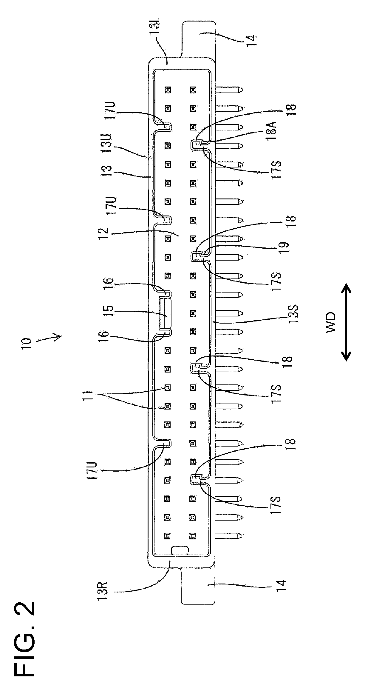
[0024]The male connector 10 is made e.g. of synthetic resin, and includes a terminal holding portion 12 for holding male terminals 11. A receptacle 13 projects forward from the periphery of the terminal holding portion 12 and surrounds male terminals 11, as shown in FIG. 2.

[0025]The male terminals 11 are arranged substantially side by side in a width direction WD at upper and lower stages in the terminal holding portion 12. Each male terminal 11 is formed by stamping out or cutting a ...

second embodiment

[0067]The guiding surfaces 61 are formed at the front ends of the engaging projections 52 in the However, the invention is not limited to this and the guiding surfaces may not be formed although the engaging projections may be more likely to get caught by the receptacle 13.

[0068]The clearance between the upper surface of the female connector 20 and the upper wall 13U of the receptacle 13 preferably is substantially equal to that between the engageable portions 18, 51 and the engaging projections 28, 52 in the above embodiments. However, the invention is not so limited and the two clearances need not be equal as long as these clearances are formed such that, even if the female connector first comes into contact with either one of the upper and lower walls of the receptacle, it immediately comes into contact with the other wall.


PUM


Abstract

With two connectors (10, 20) properly connected, engaging projections (28) projecting from wall surfaces of lower receiving grooves (27S) are inserted below engageable portions (18) provided on lower reinforcing ribs (17S) and these engaging projections (28) can be held in contact with the engageable portions (18) from below. Thus, if an upward force acts on the female connector (20), the engaging projections (28) contact the engageable portions (18) and this force is borne by the lower reinforcing ribs (17S). In other words, since the upward force acting on the female connector (20) is borne by both upper and lower walls (13U, 13S) of a receptacle (13), the upper wall (13U) can be made thinner as compared to the case where this force acts only on the upper wall (13U). As a result, a board connector (C1) can be thinned further.

Description

BACKGROUND OF THE INVENTION[0001]1. Field of the Invention[0002]The invention relates to a connector assembly with a first connector to be mounted to an electric or electronic device, such as a circuit board, and a second connector to be connected with the first connector.[0003]2. Description of the Related Art[0004]U.S. Pat. No. 7,134,910 discloses a board connector assembly with first and second connectors. The first connector includes a tubular receptacle and is mountable on a circuit board. The second connector is fittable into the receptacle.[0005]An upward force can act on the connector assembly, for example, when a wire drawn out from the second connector is bent and pulled up away from the circuit board when the two connectors are connected properly. In this situation, the second connector contacts the upper wall of the receptacle and exerts an upward force on the upper wall of the receptacle. Thus, the upper wall must have a specified strength to avoid being cracked or dama...

Claims


Application Information

Patent Timeline
IPC IPC(8): H01R13/64H01R12/71H01R13/46H01R13/516
CPCH01R12/712H01R13/6456H01R13/40
Inventor AIHARA, TETSUYA
Owner SUMITOMO WIRING SYST LTD
Learn More