
Backlight unit for liquid crystal display device

Active Publication Date: 2009-07-02
SAMSUNG ELECTRONICS CO LTD
View PDF24 Cites 13 Cited by
  • Summary
  • Abstract
  • Description
  • Claims
  • Application Information

AI Technical Summary

Benefits of technology

[0011]The present invention has been made to solve the foregoing problems with the prior art, and therefore the present invention provides an edge type backlight unit for a liquid crystal display device, advantageous for making a product thinner, and capable of implementing an effective local dimming.
[0022]As set forth above, according to the present invention, the backlight unit for a liquid crystal display device is advantageous for making a product thinner, and is capable of implementing effective local dimming.

Problems solved by technology

However, the backlight unit using the CCFL has some defects.
For example, it is difficult to implement partial driving such as local dimming or impulsive driving; the use of mercury creates environmental pollution; response rate is slow.
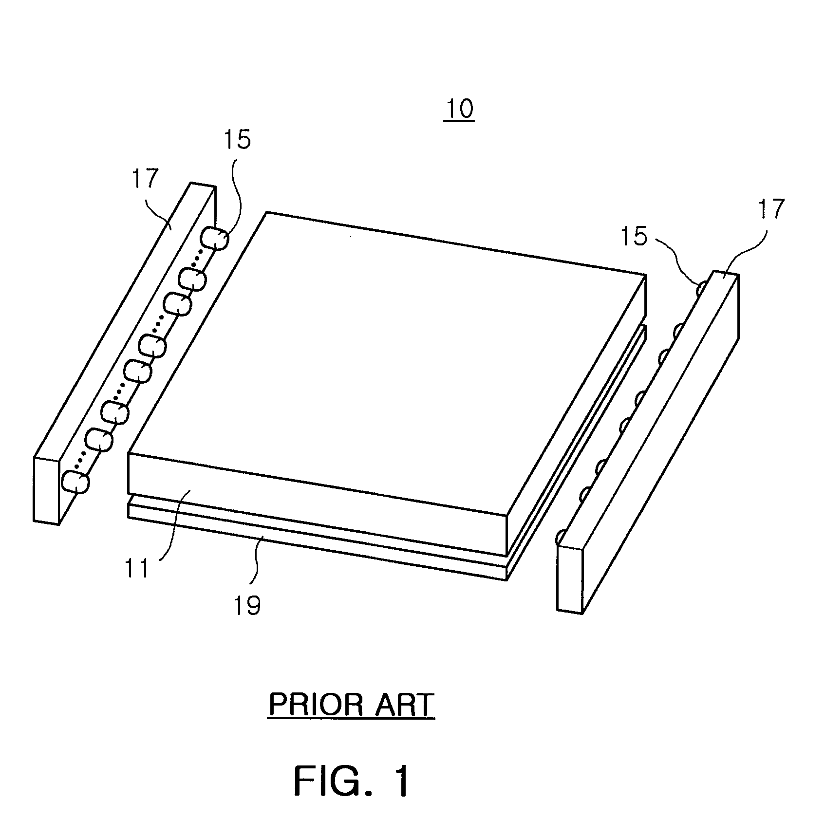
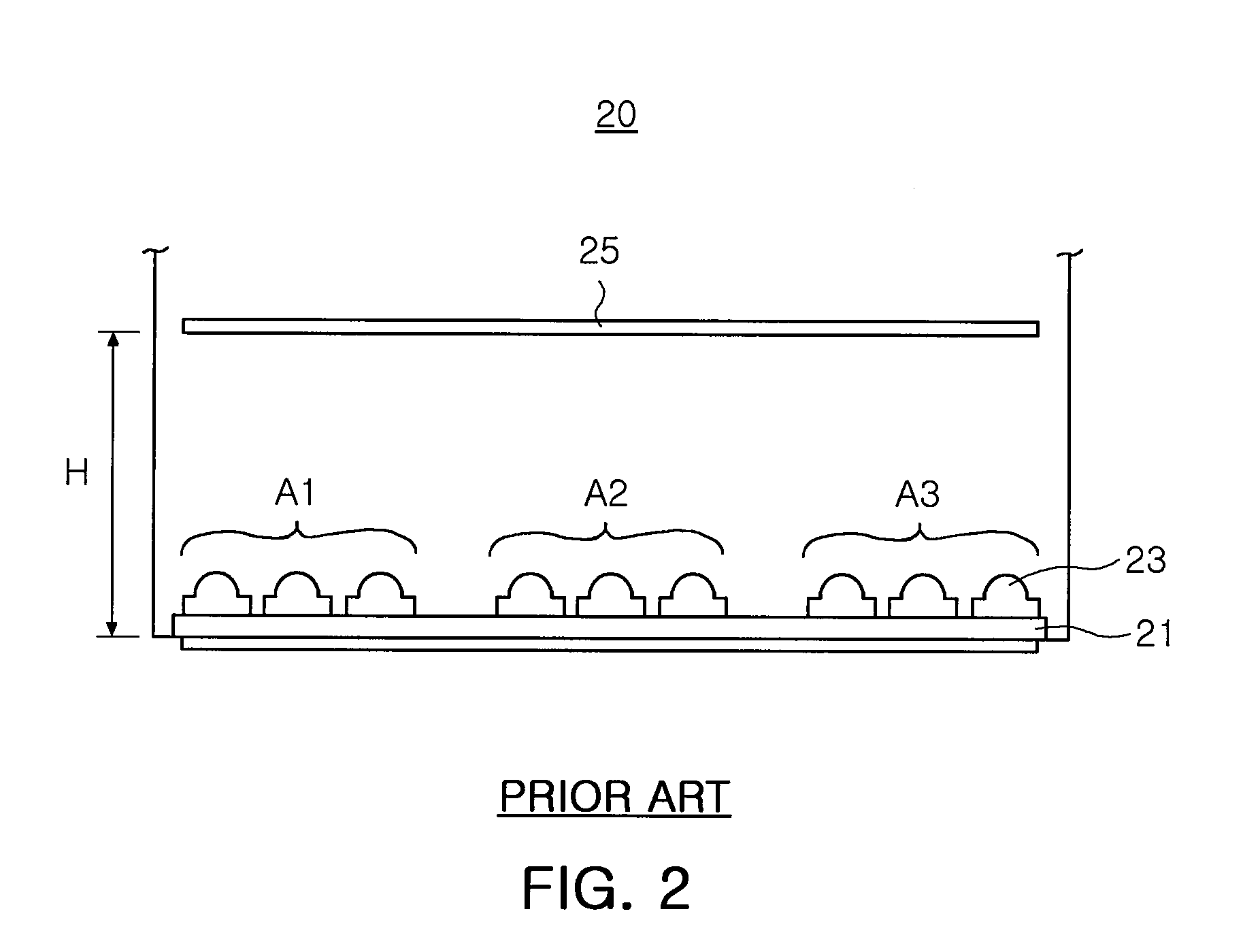
However, in the case of individually driving the respective LEDs 23, a problem arises in high power consumption, high cost for protection against high temperature, complexity of a circuit, or others.
In the case of driving for the respective regions, a problem occurs in that local dimming effect is relatively deteriorated due to the difficulty in fine division into regions and also a thickness H of the backlight unit.
Particularly, since a sufficient thickness H corresponding to an optical thickness is needed to secure uniformity of light, it is disadvantageous to make the backlight unit (and further the LCD device) thinner.

Method used


Image

  • Backlight unit for liquid crystal display device
  • Backlight unit for liquid crystal display device
  • Backlight unit for liquid crystal display device

Examples


Embodiment Construction

[0033]Preferred embodiments of the present invention will be described herein below with reference to the accompanying drawings. However, the embodiments of the invention may be changed into other diverse forms, and the present invention is not limited thereto. Furthermore, the embodiments are provided to those skilled in the art only for illustrative purpose. Throughout the drawings, the shapes, the sizes or so of the components may thus be exaggerated for more clear explanation, and like reference numbers are used to depict the same or similar elements, features and structures.

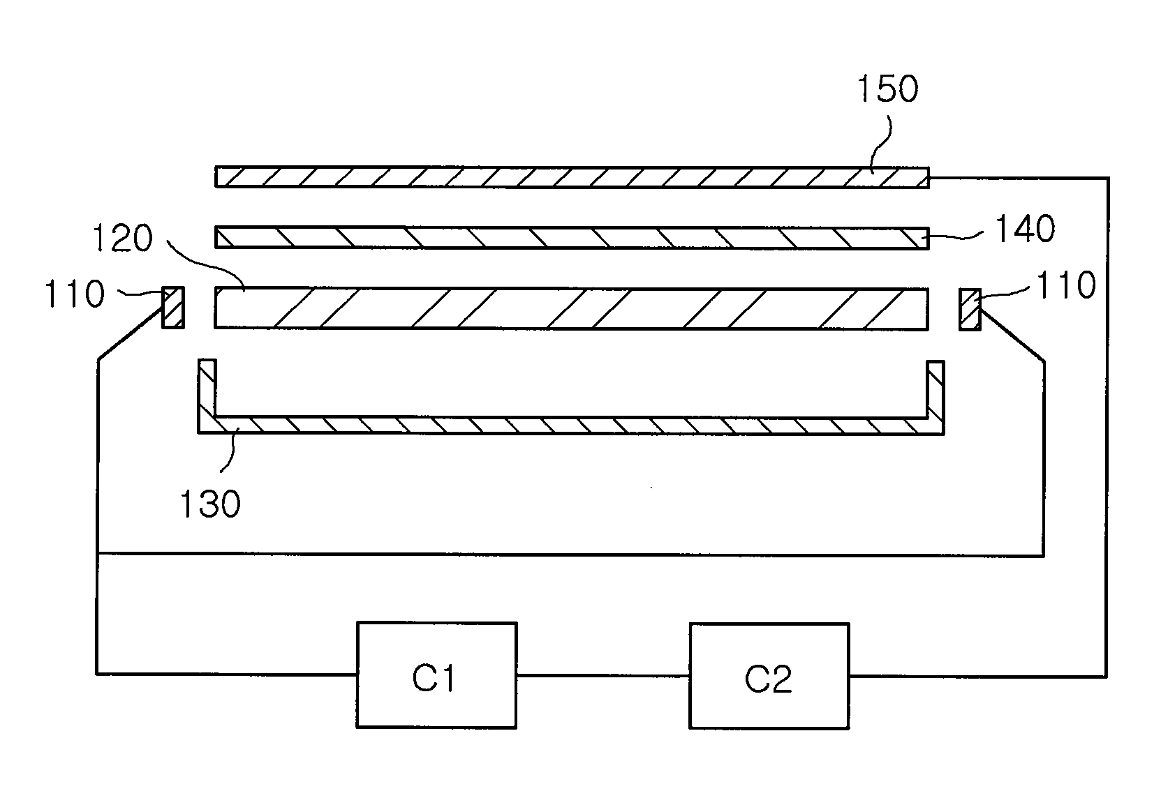
[0034]FIG. 3 is a sectional view illustrating a backlight unit according to an embodiment of the present invention, wherein respective components thereof are shown in exploded form, FIG. 4 is a plan view illustrating a light guide plate and an LED array shown in FIG. 3, and FIG. 5 is a plan view illustrating a light guide plate and an LED array modified from the embodiment shown in FIG. 4.

[0035]Referring fir...


PUM


Abstract

A backlight unit for a liquid crystal display (LCD) device, disposed under a liquid crystal panel to illuminate the liquid crystal panel. The backlight unit includes a light guide plate, first and second light emitting diode (LED) arrays, disposed on adjacent sides, perpendicular to each other, of the light guide plate, each array having a plurality of LED blocks, consisting of one or more LEDs, and a control unit that controls electric signals, respectively inputted to the LED blocks, to regulate luminance for the respective LED blocks, wherein light emitted from the first and second LED arrays is overlapped each other in the light guide plate.

Description

CROSS-REFERENCE TO RELATED APPLICATIONS[0001]This application claims the priority of Korean Patent Application No. 2007-0139197, filed on Dec. 27, 2007, in the Korean Intellectual Property Office, the disclosure of which is incorporated herein by reference.BACKGROUND OF THE INVENTION[0002]1. Field of the Invention[0003]The present invention relates to a backlight unit for liquid crystal display devices using a light emitting diode (LED) and a light guide plate and, more particularly, to a backlight unit for liquid crystal display devices, which can implement local dimming using an edge light source.[0004]2. Description of the Related Art[0005]According to the recent trend of making an image display device have a slim size and high performance, a liquid crystal display (LCD) device has been widely used in a TV, a monitor, and others. Since a liquid crystal panel cannot emit light by itself, the LCD device needs an LCD backlight unit (hereinafter referred to as ‘a backlight unit’). A ...

Claims


Application Information

Patent Timeline
IPC IPC(8): F21V7/04
CPCG02B6/0068G02B6/0073G02B6/0078G02F1/133615G02F1/133603G02F1/133G02F1/1335
Inventor KIM, DAE HYUNHAHM, HUN JOOKIM, HYUNG SUKKIM, DAE YEON
Owner SAMSUNG ELECTRONICS CO LTD
Learn More