

Combination Toothbrush, Floss Dispenser and Tongue Scraper
- Summary
- Abstract
- Description
- Claims
- Application Information
AI Technical Summary
Benefits of technology
Problems solved by technology
Method used
Image

Examples
Embodiment Construction
[0038]Persons of ordinary skill in the art will realize that the following disclosure is illustrative only and not in any way limiting. Other embodiments of the disclosure will readily suggest themselves to such skilled persons having the benefit of this disclosure.
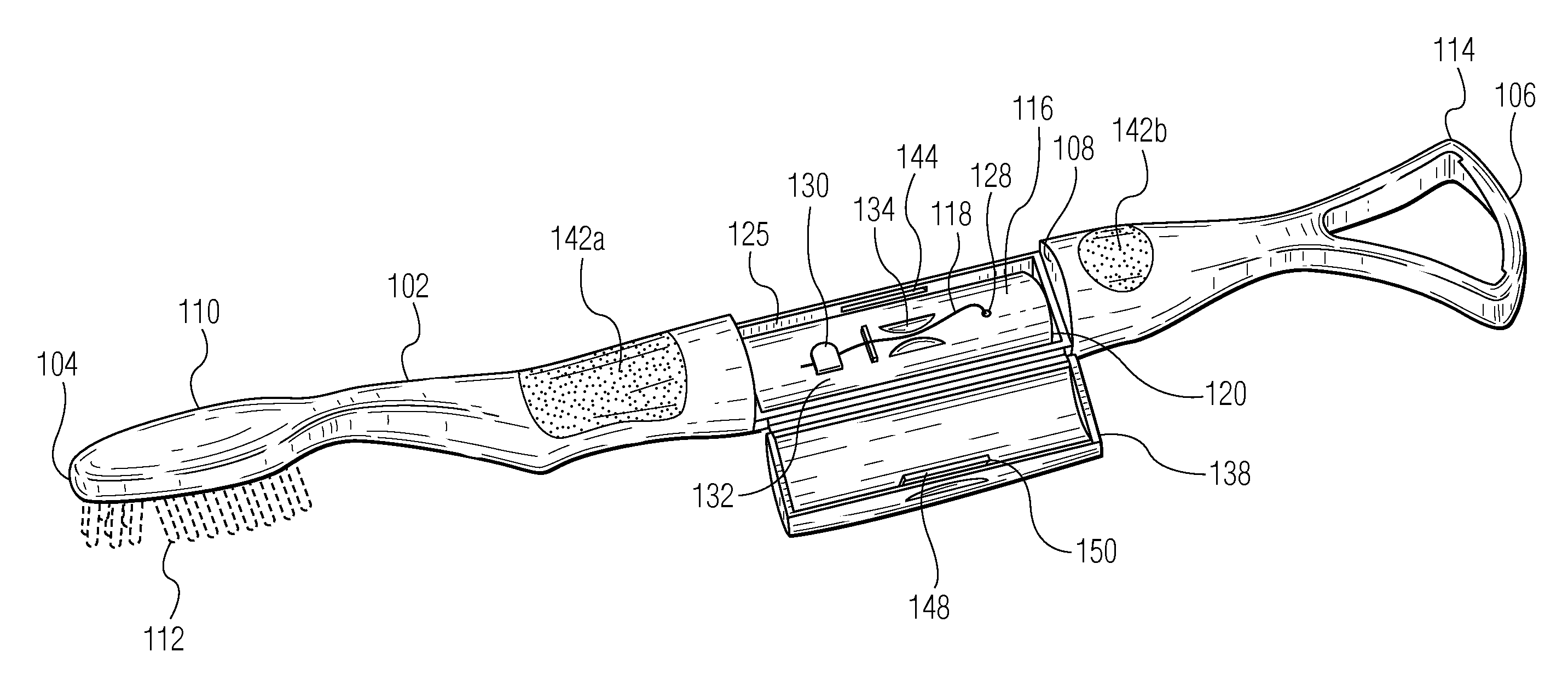
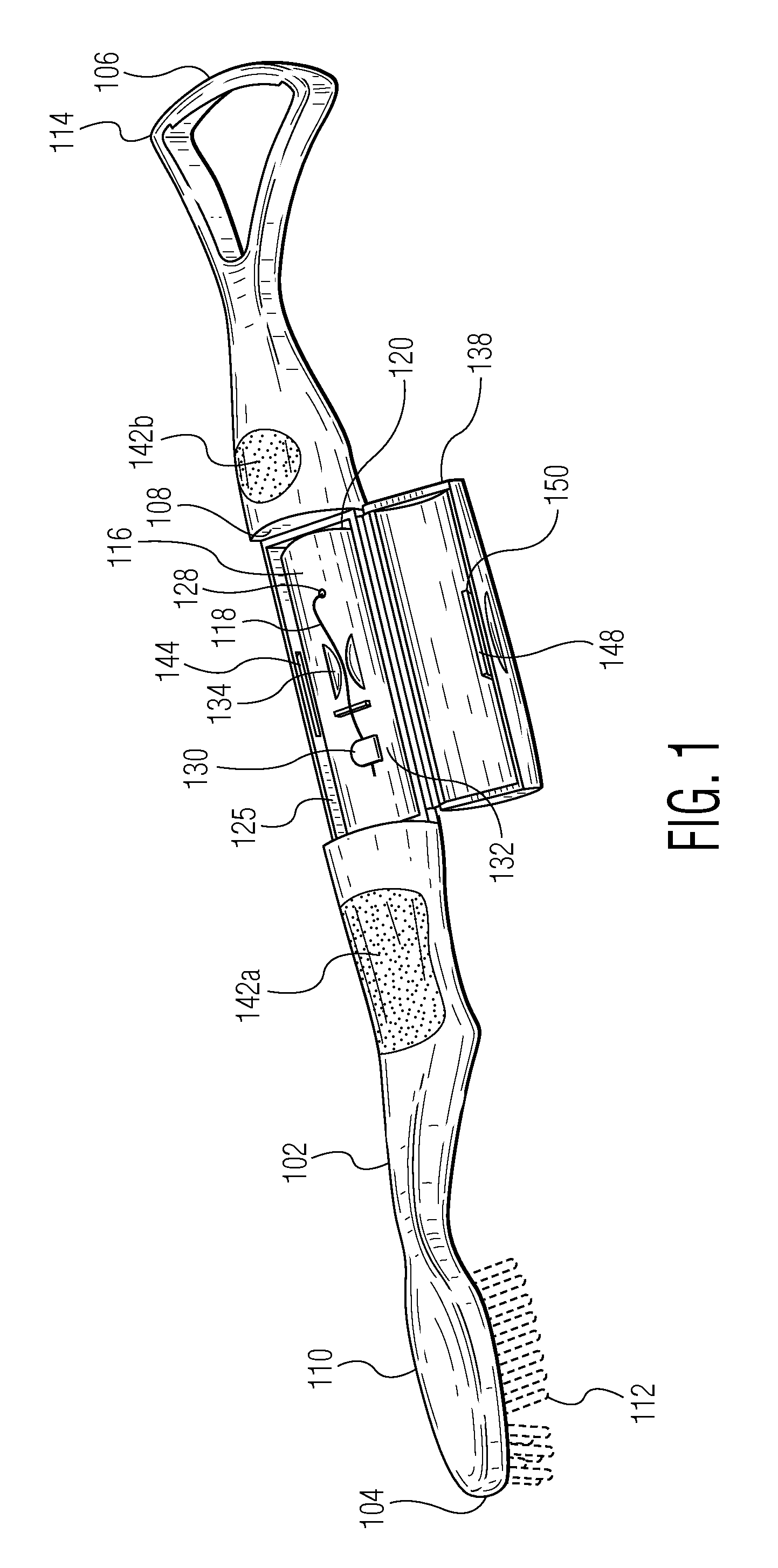
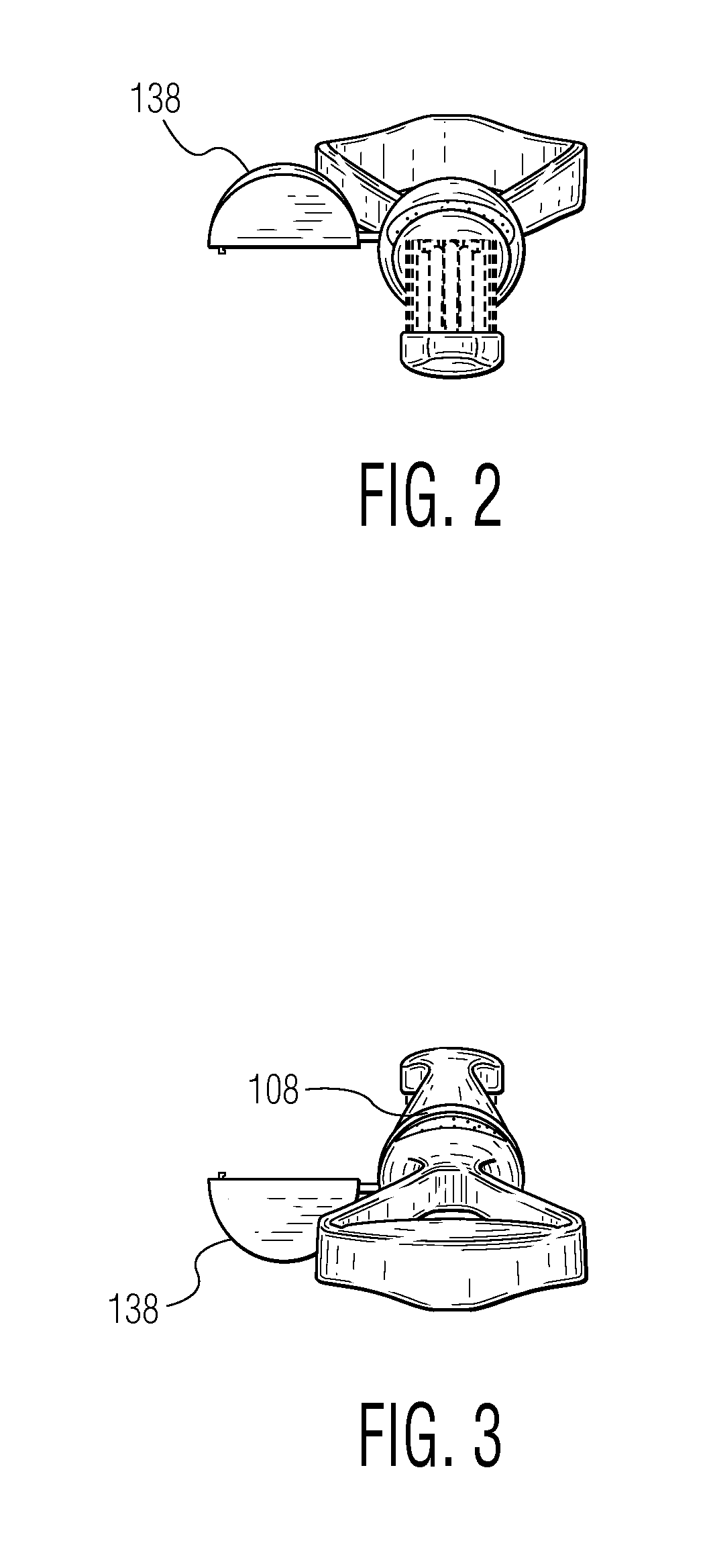
[0039]The present disclosure is generally directed to embodiments of a combination toothbrush and tongue scraper with a floss dispenser in a handle between the brush and the tongue scraper.
[0040]Referring initially to FIG. 1, the basic constructional details, principles of operation and arrangement of an exemplary combination toothbrush, floss dispenser and tongue scraper apparatus 100 according to a preferred embodiment of the present invention will be discussed.
[0041]In FIG. 1, a combination toothbrush, tongue scraper and floss dispenser apparatus 100 according to a preferred embodiment of the present invention is provided. In FIG. 1, the combination toothbrush, tongue scraper and floss dispenser apparatus 100 comprises...
PUM
 Abstract
Description
Claims
Application Information