
Toe correct bush

a bush and correct technology, applied in the field of toe correct bush, can solve the problems of deformation and damage of damage to the intermediate restraining member, insufficient improvement of running stability, etc., and achieve the effect of improving durability and improving running stability of the vehicl

Active Publication Date: 2013-01-03
SUMITOMO RIKO CO LTD
View PDF6 Cites 4 Cited by
  • Summary
  • Abstract
  • Description
  • Claims
  • Application Information

AI Technical Summary

Benefits of technology

The patent is about a device that improves the way a vehicle runs by using a rubber material to correct the toe. The device has two parts, one that is attached to the rubber material and another that is attached to a connecting rubber material. This prevents the device from getting deformed when the rubber materials have different shapes. This makes the device stronger and more durable.

Problems solved by technology

However, application of such an annular planar intermediate restraining member to the toe correct bush having the inclined portions as disclosed in Patent Literature 2 may deform and damage the intermediate restraining member at maximum load input in a tilt direction.
Then, a greater strain may be exerted on the intermediate restraining member depending on the difference in the shape of the compression rubber and the connecting rubber, thus damaging the intermediate restraining member.
However, tilt displacement is unlikely to occur between the inner shaft member and the outer tubular member, thus leading to insufficient effects in improvement in running stability and the like from the toe correction function.

Method used


Image

  • Toe correct bush
  • Toe correct bush
  • Toe correct bush

Examples


Embodiment Construction

[0039]An embodiment of the present invention is described below with reference to the drawings.

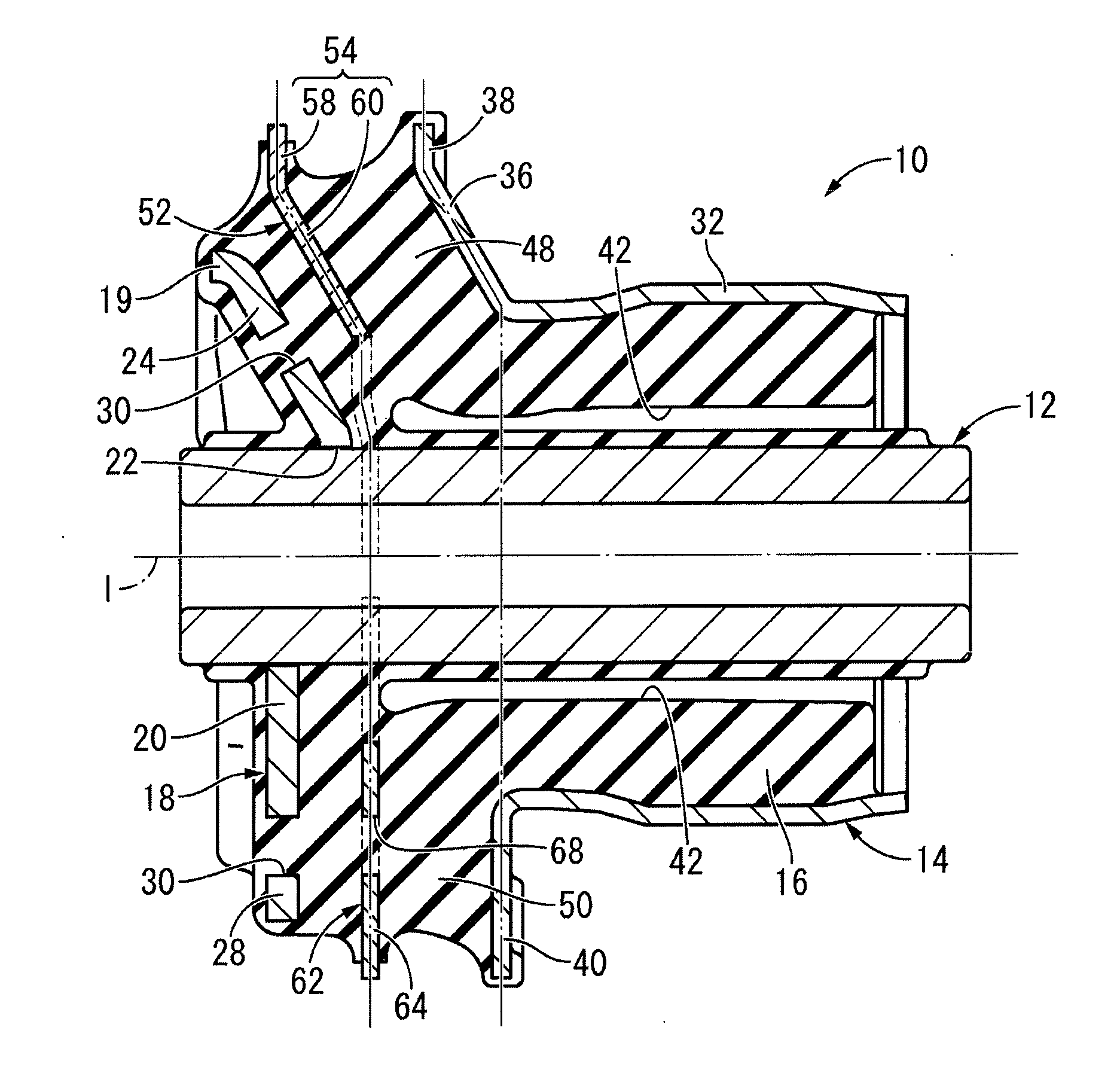
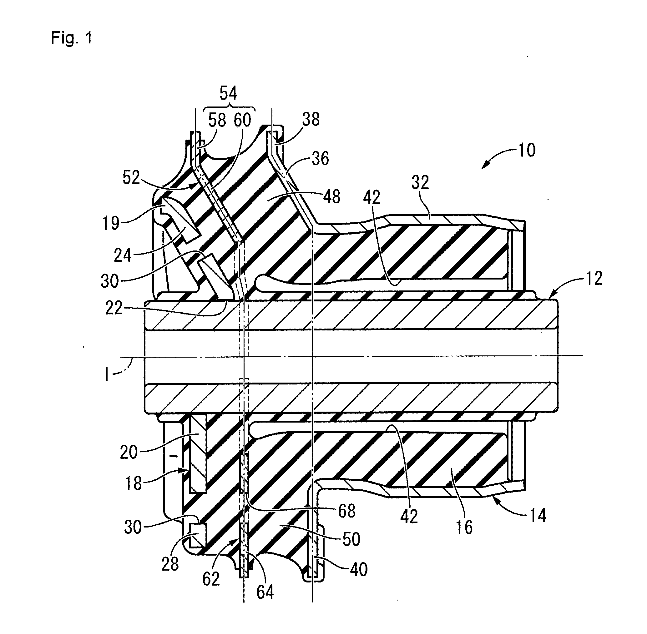
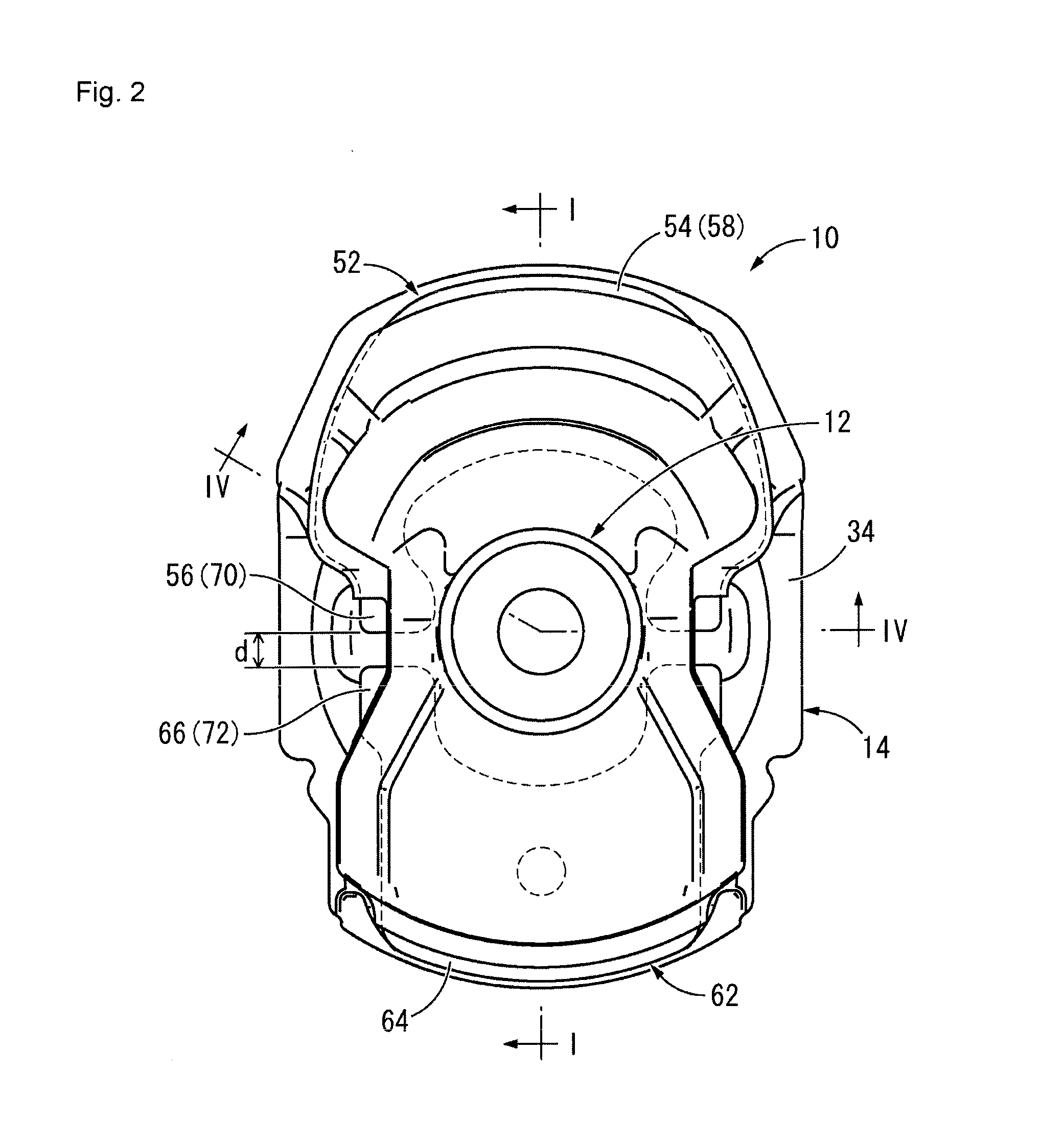
[0040]A toe correct bush 10 according to the embodiment of the present invention is illustrated in FIGS. 1 to 4. The toe correct bush 10 has an inner shaft member 12 and an outer tubular member 14 inserted around the external thereof with a predetermined distance between the members. The inner shaft member 12 and the outer tubular member 14 are elastically connected by a main rubber elastic body 16. In the description below, a vertical direction basically refers to a vertical direction in FIG. 1.

[0041]More specifically, the inner shaft member 12 has a substantially tubular shape having a small diameter, as shown in FIGS. 5 and 6. A planar fixing plate 18 is fixed proximate to one end portion in a shaft direction. The fixing plate 18 has a plate shape provided with a reinforcement rib 19 along its periphery excluding a lower end, the reinforcement rib 19 projecting in a thickness direction,...


PUM

PropertyMeasurementUnit
elasticaaaaaaaaaa
distanceaaaaaaaaaa
running stabilityaaaaaaaaaa

Abstract

To provide a toe correct bush having excellent durability and a novel structure, the toe correct bush effectively achieving improvement in running stability during steering with a toe correction function and improvement in straight line performance with an intermediate restraining plate. A first intermediate restraining member is provided between opposing surfaces of an inner inclined portion and an outer inclined portion and is fixed to a compression rubber, the first intermediate restraining member spreading and being isolated from the opposing surfaces of the inner inclined portion and the outer inclined portion. A second intermediate restraining member is provided independent from the first intermediate restraining member between opposing surfaces of an inner flange and an outer flange and is fixed to a connecting rubber, the second intermediate restraining member spreading and being isolated from the opposing surfaces of the inner flange and the outer flange.

Description

CLAIM FOR PRIORITY [0001]This application is a continuation of PCT / JP2011 / 004952 filed Sep. 5, 2011, and claims the priority benefit of Japanese Application No. 2010-218278, filed Sep. 29, 2010, the contents of which is expressly incorporated by reference in its entirety.TECHNICAL FIELD [0002]The present invention relates to a toe correct bush, which is a type of suspension bush of a vehicle. The present invention relates in particular to a toe correct bush having a novel structure suitably used in a torsion beam rigid axle suspension mechanism and mounted on each of left and right trailing arms in a portion attached to a body.BACKGROUND ART [0003]A toe correct bush as disclosed in Japanese Patent Laid-Open Publication No. 2006-46588 (Patent Literature 1), for example, is known as a conventional type of suspension bush mounted on each of left and right trailing arms in a portion attached to a body, the trailing arms being connected by a torsion beam in a torsion beam rigid axle susp...

Claims


Application Information

Patent Timeline
Patent Type & Authority Applications(United States)
IPC IPC(8): B60G11/22
CPCF16F1/3876B60G7/02B60G2200/462B60G2204/4106B60G2204/41B60G2204/4104B60G2204/143
Inventor YAMADA, RYUSUKENAKAMURA, YORIKAZU
Owner SUMITOMO RIKO CO LTD
Learn More