Input Voltage Sensing For A Switching Power Converter And A Triac-Based Dimmer

a technology of input voltage and triac, which is applied in the field of electronic systems, can solve the problems of triac-based dimmer prematurely connecting and disconnecting the input voltage, unable to and unable to accurately determine the phase cut angle of the input voltag

Inactive Publication Date: 2013-01-03
SIGNIFY HLDG BV
View PDF2 Cites 38 Cited by
  • Summary
  • Abstract
  • Description
  • Claims
  • Application Information

AI Technical Summary

Benefits of technology

[0018]In another embodiment of the present invention, a controller to control a switching power converter of a lighting system. The controller is capable to generate a control signal to control probing an output of a triode for alternating current (“triac”) based dimmer every Nth half cycle of an alternating current (AC) output voltage of the dimmer to allow the controller to sense the output voltage from a time when the triac connects an input voltage source to an output of the dimmer until an occurrence of a predetermined event. N is an integer greater than 1. The controller is further capable to sense the output voltage from the time when the triac connects an input voltage source to an output of the dimmer until an occurrence of a predetermined event.
[0019]In a further embodiment of the present invention, a method includes discharging parasitic capacitors in a power and lighting control system to allow sensing of a dimmer output voltage of a dimmer that tracks an input voltage to the dimmer. The method further includes sensing the dimmer output voltage
[0020]In another embodiment of the present invention, an apparatus includes a parasitic discharge circuit coupled to a dimmer in a power and lighting control system. The parasitic discharge circuit is capable to discharge parasitic capacitors in the power and lighting control system to allow sensing of a dimmer output voltage of the dimmer that tracks an input voltage to the dimmer.

Problems solved by technology

However, determining the phase cut angle of the input voltage has proved challenging, especially when attempting to retain the energy efficiency of the electronic lighting devices.
However, without intervention a triac-based dimmer tends to improperly connect and disconnect the input voltage to the electronic lighting device multiple times during a single half cycle of the input voltage.
Consequently, without intervention the electronic lighting device may draw less than the hold current causing the triac to prematurely connect and disconnect the input voltage to the load during a phase cut when the triac should remain nonconductive.
Additionally, some circuits can cause the triac to prematurely disconnect after the phase cut of the input voltage.
Improper functioning of the triac-based dimmer can cause difficulties in detecting the zero crossings of the input voltage.
Improper or non-detection of the zero crossings of the input voltage can be disruptive to the proper operation of the controller in controlling the electronic lighting devices.

Method used


Image

  • Input Voltage Sensing For A Switching Power Converter And A Triac-Based Dimmer
  • Input Voltage Sensing For A Switching Power Converter And A Triac-Based Dimmer
  • Input Voltage Sensing For A Switching Power Converter And A Triac-Based Dimmer

Examples


Embodiment Construction

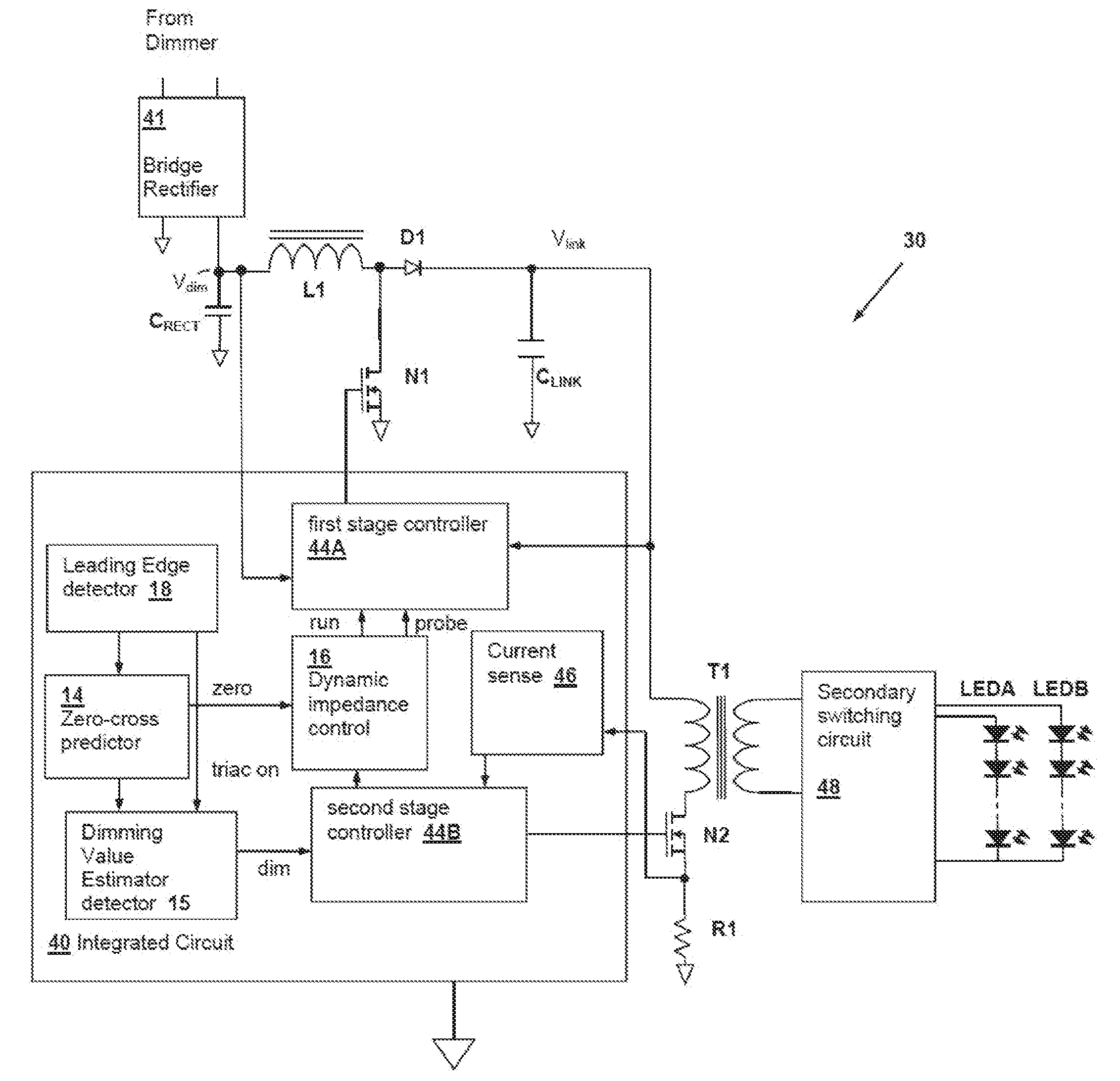
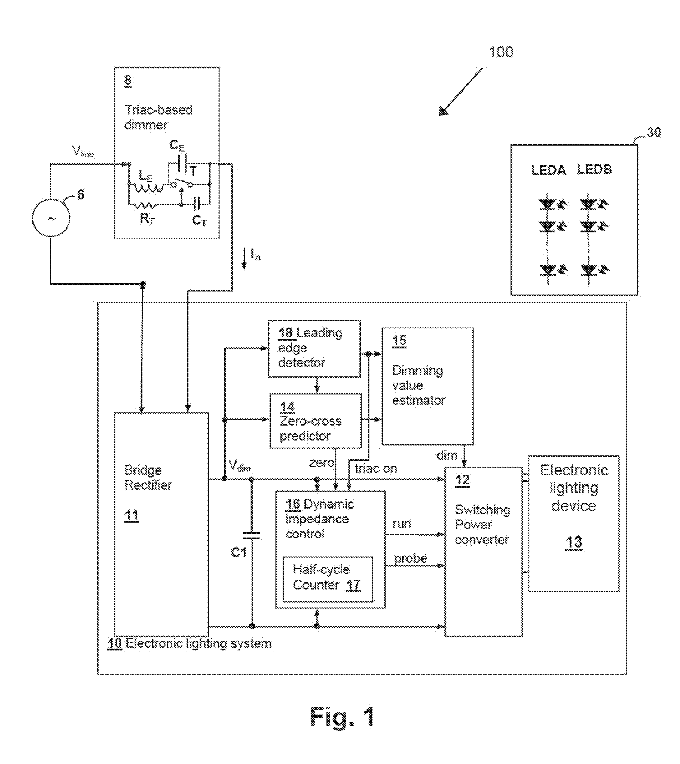
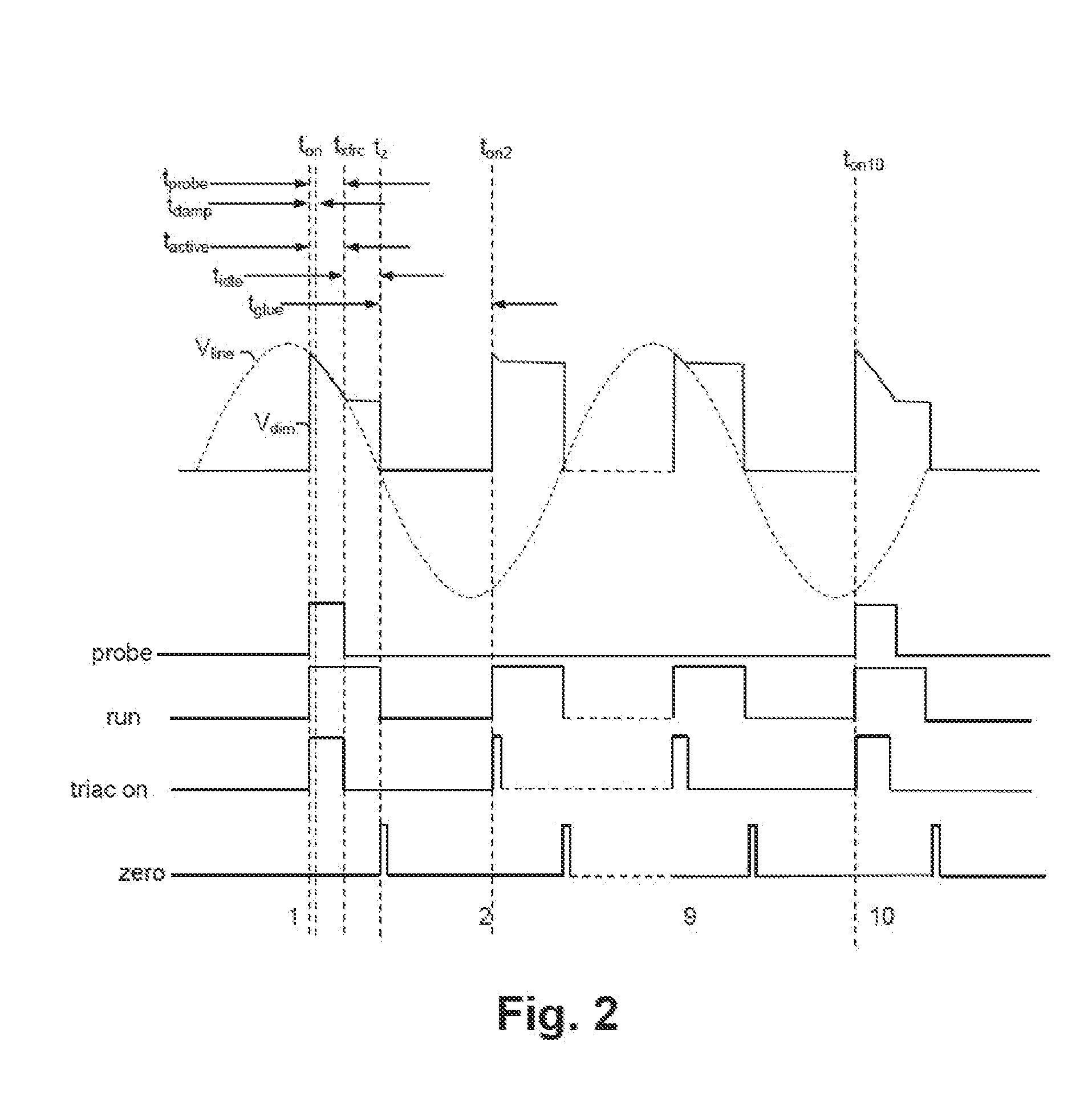
[0031]An electronic lighting system and method described herein control energy provided to an electronic lighting device, such as one or more light-emitting diodes (LEDs) and / or compact fluorescent lamps (CFLs), of the electronic lighting system. A triac-based dimmer phase cuts an input voltage provided to the electronic lighting system. A controller of the electronic lighting system utilizes a probing circuit to overcome idiosyncrasies of the triac-based dimmer to prevent the dimmer from prematurely disconnected and, thus, allowing the controller to sense a dimmer output voltage. To reduce energy consumption, rather than probing each cycle of the output voltage of the triac-based dimmer, the controller periodically or intermittently probes the output voltage of the triac-based dimmer.

[0032]In at least one embodiment, energy supplied to the electronic lighting devices is varied in accordance with a dimming value determined from a phase cut angle of an alternating current (AC) input ...


PUM


Abstract

An electronic lighting system and method described herein control energy provided to an electronic lighting device, such as one or more light-emitting diodes (LEDs) and/or compact fluorescent lamps (CELs), of the electronic lighting system. A triac-based dimmer phase cuts a line voltage provided to the electronic lighting system. A controller of the electronic lighting system utilizes a probing system to overcome idiosyncrasies of the triac-based dimmer to allow the controller to probe and sense the line voltage. To reduce energy consumption, rather than probing each cycle of the output voltage of the triac-based dimmer, the controller periodically or intermittently probes the output voltage of the triac-based dimmer.

Description

CROSS-REFERENCE TO RELATED APPLICATION[0001]The present U.S. Patent Application claims priority under 35 U.S.C. §119(e) to U.S. Provisional Patent Application No. 61 / 503,357, filed Jun. 30, 2011, which is incorporated herein by reference.[0002]The present U.S. Patent Application is a continuation-in-part and claims priority under 35 U.S.C. §120 to:[0003]1. U.S. patent application Ser. No. 12 / 858,164 entitled “DIMMER OUTPUT EMULATION”, filed Aug. 17, 2010, inventor John L. Melanson (referred to herein as “Melanson I”);[0004]2. U.S. patent application Ser. No. 13 / 19.4,531 entitled “POWERING HIGH-EFFICIENCY LIGHTING DEVICES FROM A TRIAC-BASED DIMMER”, filed on Jul. 29, 2011;[0005]3. U.S. patent application Ser. No. 13 / 217,174, entitled: “MULTI-MODE DIMMER INTERFACING INCLUDING ATTACH STATE CONTROL”, filed Aug. 24, 2011, and inventors: Eric J. King and John L. Melanson, which claims priority under 35 U.S.C. §119(e) to U.S. Provisional Patent Application No. 61 / 376,504, filed Aug. 24, 20...

Claims


Application Information

Patent Timeline
Patent Type & Authority Applications(United States)
IPC IPC(8): H05B37/00H05B44/00
CPCH05B33/0815Y02B20/346H05B33/0848H02M1/4225H02M3/33507H02M5/257H05B45/14Y02B20/30Y02B70/10H05B45/3725H05B45/385H02M1/007
Inventor HE, ZHAOHUISINGH, RAHULKING, ERIC J.MELANSON, JOHN L.DRAPER, WILLIAM A.
Owner SIGNIFY HLDG BV
Why Eureka
Try Eureka