Microfluidic channel for removing bubbles in fluid

Inactive Publication Date: 2013-01-03
SAMSUNG ELECTRONICS CO LTD
View PDF4 Cites 18 Cited by
  • Summary
  • Abstract
  • Description
  • Claims
  • Application Information

AI Technical Summary

Benefits of technology

[0013]Due to the channel having a gradually expanded structure by the gradually increas

Problems solved by technology

As a result, the bubbles can partially or even totally block the microfluidic channel, which impedes the flow of the fluid and makes the fluid more difficult to control.
Al

Method used


Image

  • Microfluidic channel for removing bubbles in fluid
  • Microfluidic channel for removing bubbles in fluid
  • Microfluidic channel for removing bubbles in fluid

Examples


example

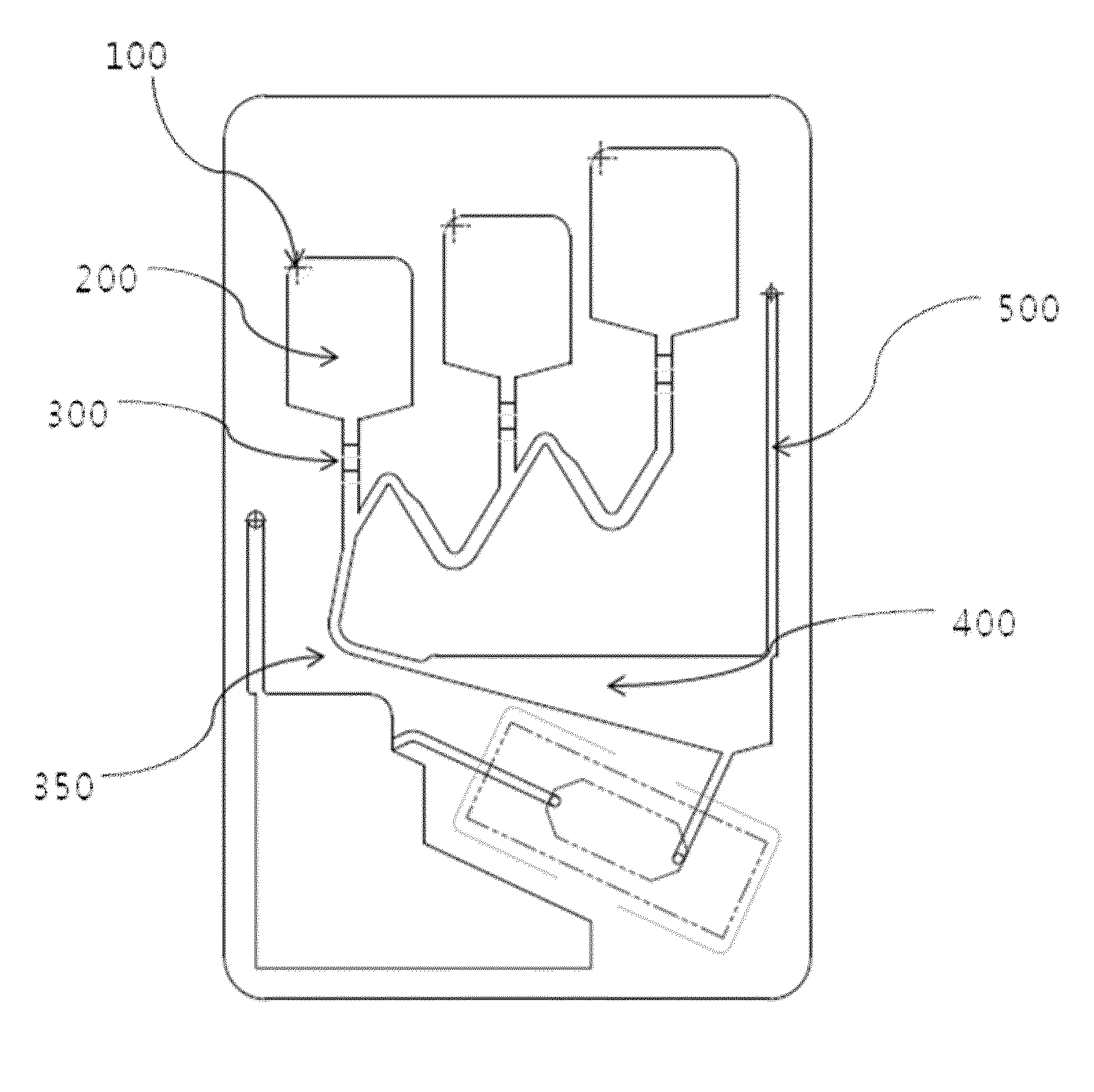
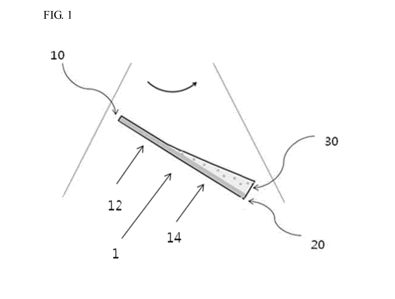
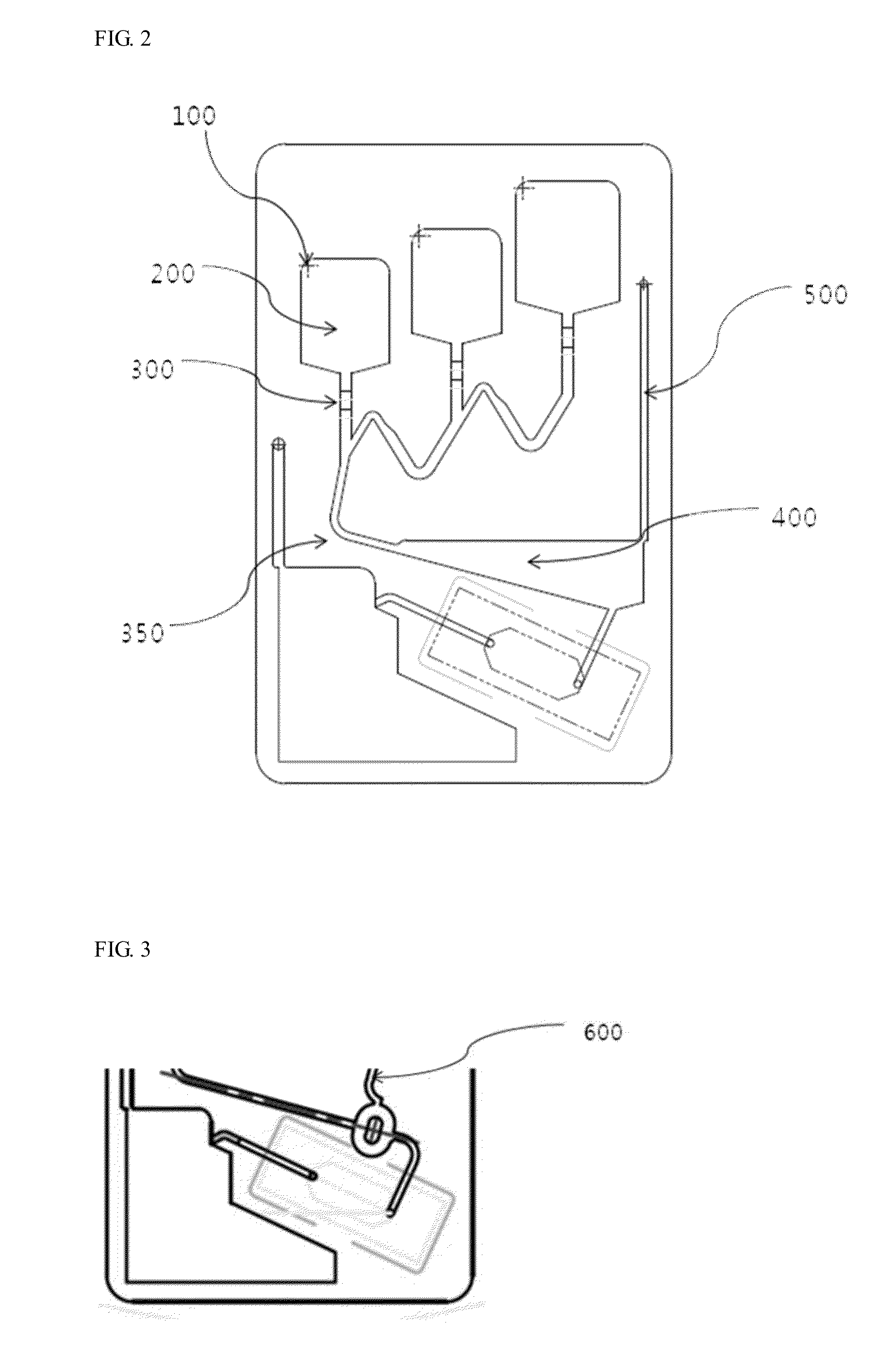
[0102]Removal of Bubbles from a Microfluidic Channel Having a Gradually Expanded Cross-Sectional Area

[0103]The same method is performed as in Comparative example, and results are shown in FIGS. 6 through 9.

[0104]From FIGS. 6 through 8, it is observed that a gas is separated from a liquid due to a difference between pressures applied to the gas and the liquid in a microfluidic channel, and is moved to the top of the microfluidic channel, as indicated by the white outlined boxes. While moving toward a ventilating hole connected to the outside of a cartridge, the separated gas of FIG. 9 is removed.

[0105]Therefore, it can be seen that bubbles are effectively removed in the microfluidic channel having the gradually expanded cross-sectional area.


PUM


Abstract

A microfluidic channel for effectively removing a gas from a fluid, and microfluidic apparatus including the same are provided. The microfluidic channel includes a first channel having a uniform cross-sectional area, and a second channel connected to the first channel and having a gradually expanded cross-sectional area.

Description

CROSS-REFERENCE TO RELATED APPLICATION[0001]This application claims priority to Korean Patent Application No. 10-2011-0063954, filed on Jun. 29, 2011, and all the benefits accruing therefrom under 35 U.S.C. §119, the content of which in its entirety is herein incorporated by reference.BACKGROUND[0002]1. Field[0003]Provided is a microfluidic channel for removing bubbles in a fluid and a microfluidic apparatus including the same.[0004]2. Description of the Related Art[0005]There has been a growing interest in the manufacture and use of microfluidic apparatuses for the acquisition of chemical and biological information.[0006]A microfluidic apparatus is used to analyze and measure chemical, biological, or physical characteristics of a fluid on a micro-scale or meso-scale level in the fields of physics, chemistry, biochemistry and bioengineering. The microfluidic apparatus may use a small amount of reagent and shorten a reaction time.[0007]Samples and reagents, etc., used in a microfluid...

Claims


Application Information

Patent Timeline
IPC IPC(8): B01L3/00
CPCB01L3/502723B01L2200/0647B01L2200/0684B01L2300/0816Y10T436/2575B01L2400/0409B01L2400/043B01L2400/0677B01L2300/0867
Inventor LEE, WOOCHANGJUNG, JAEYEONCHOI, YOUN SUKHAHN, YOUNG KIKIM, SANG KYULEE, SOO SUK
Owner SAMSUNG ELECTRONICS CO LTD
Why Eureka
Try Eureka