Medical treatment apparatus and control method of medical treatment apparatus

a technology of medical treatment and control method, which is applied in the field of medical treatment device, medical treatment system, medical treatment method, etc., can solve problems such as difficult tissue conjugation

Inactive Publication Date: 2013-01-03
OLYMPUS CORP
View PDF14 Cites 761 Cited by
  • Summary
  • Abstract
  • Description
  • Claims
  • Application Information

AI Technical Summary

Benefits of technology

[0011]A medical treatment device to treat and join body tissues according to the present invention includes at least a pair of holding members which is configured to hold the body tissues to be treated, an energy output portion provided in at least one of the pair of holding members and connected to an energy source to form a joined portion by s

Problems solved by technology

This fact makes conjugation of tissues diffi

Method used


Image

  • Medical treatment apparatus and control method of medical treatment apparatus
  • Medical treatment apparatus and control method of medical treatment apparatus
  • Medical treatment apparatus and control method of medical treatment apparatus

Examples


first embodiment

[0083]The first embodiment will be described with reference to FIGS. 1 to 6.

[0084]For example, a linear-type surgical treatment device 12 for treatment through the abdominal wall is taken as an example of the energy treatment device (medical treatment device).

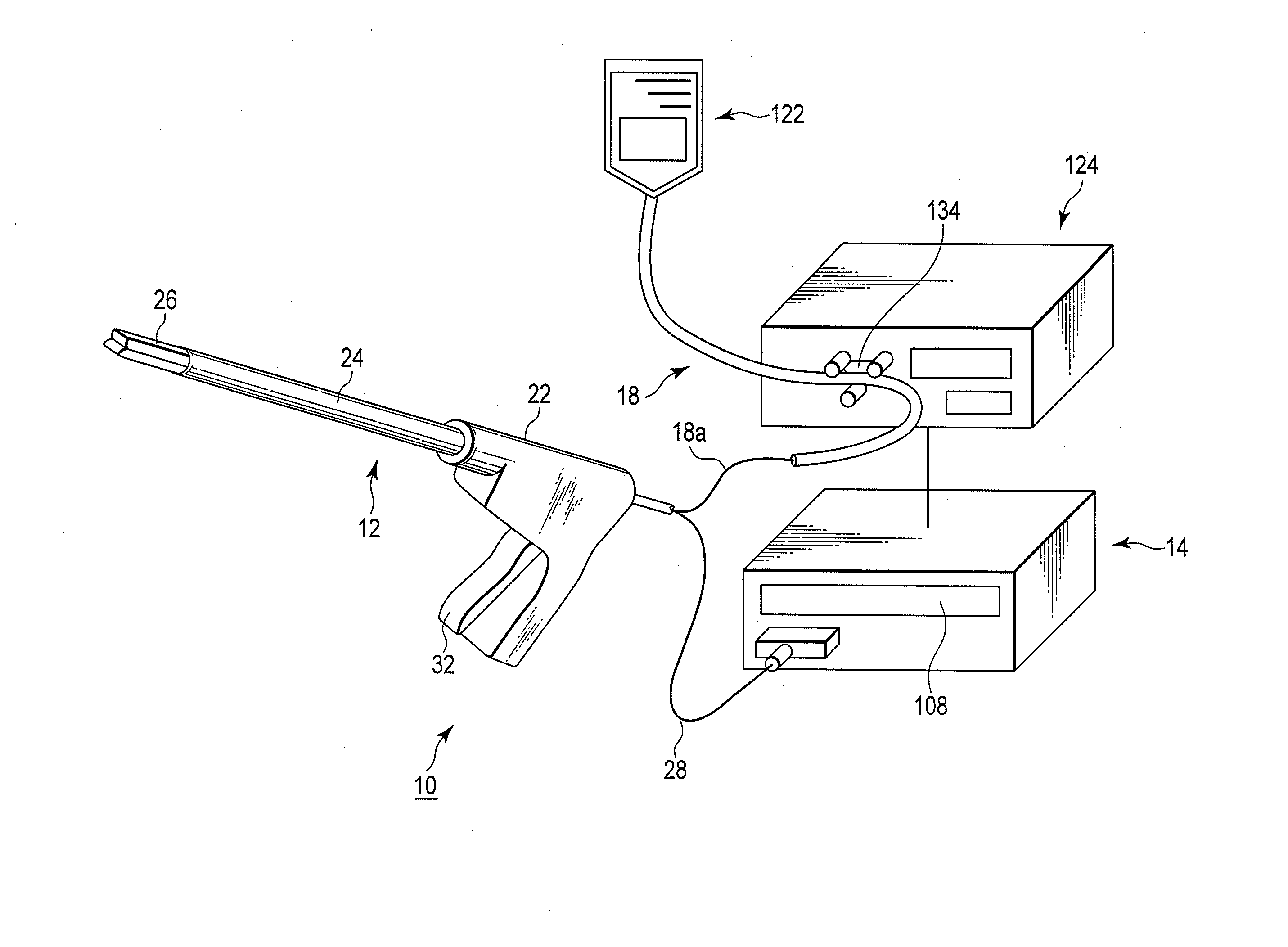
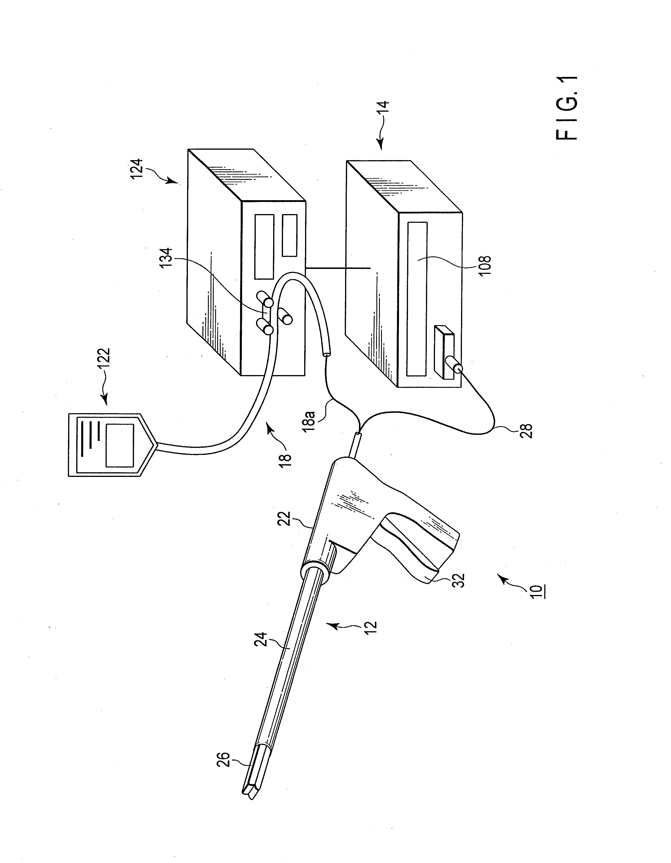
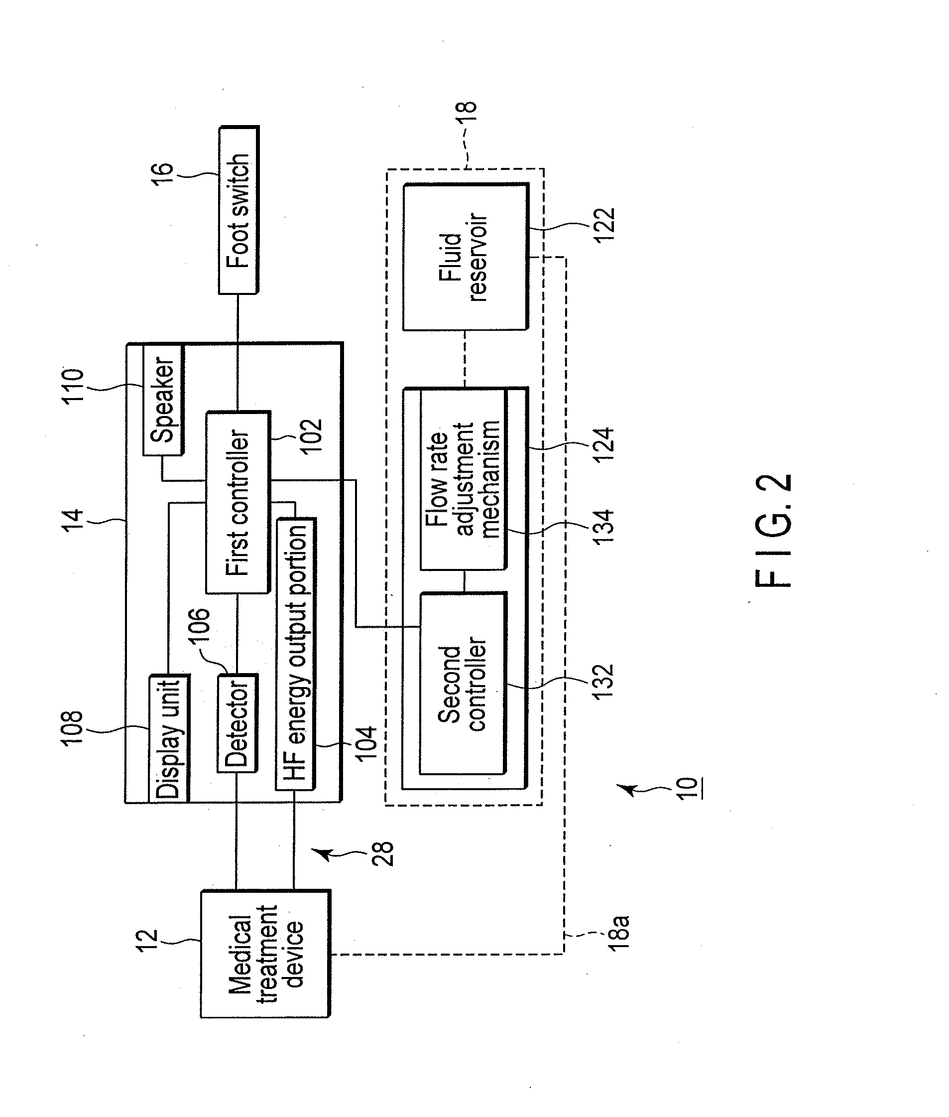
[0085]As shown in FIGS. 1 and 2, a medical treatment system 10 includes the energy treatment device 12, an energy source (control section) 14, a foot switch (or a hand switch) 16, and a fluid source 18

[0086]As shown in FIG. 1, the energy treatment device 12 includes a handle 22, a shaft 24, and a treatment portion (holding portion) 26 which is able to be opened and closed. The handle 22 is connected to the energy source 14 via a cable 28. As shown in FIG. 2, the foot switch 16 is connected to the energy source 14.

[0087]The foot switch 16 includes a pedal (not shown). A series of operations such as ON / OFF of the supply of energy (high-frequency energy in the present embodiment) from the energy source 14 to the surgical treatment...

second embodiment

[0163]Next, the second embodiment will be described using FIGS. 11A to 11C. The present embodiment is a modification of the first embodiment and the same reference numerals are attached to the same members as those used in the first embodiment or members achieving the same action as the action of those in the first embodiment and a description of such members is omitted.

[0164]Instead of a channel (recess) 62b (see FIGS. 4A to 4C), a fluid conduit 162 having insulating properties is disposed on a main body 62 of a first holding member 52 shown in FIGS. 11A to 11C. The openings 92a, 94a of the high-frequency electrodes 92, 94 described in the first embodiment are removed.

[0165]The fluid conduit 162 is disposed on a ring shape in a position close to the surface of the high-frequency electrode 92 along edges of the outer circumference of the main body 62. As shown in FIG. 11C, the transverse section of the fluid conduit 162 is formed, for example, in a circular shape or rectangular shap...

third embodiment

[0171]Next, the third embodiment will be described using FIGS. 12 to 16. The present embodiment is a modification of the first and second embodiments and the same reference numerals are attached to the same members as those used in the first and second embodiments or members achieving the same action as the action of those in the first and second embodiments and a description of such members is omitted.

[0172]As shown in FIG. 12, a handle 22 of an energy treatment device 12b includes a cutter driving knob 34 to move a cutter (auxiliary treatment device) 180 described later while being installed adjacent to the treatment portion opening / closing knob 32.

[0173]As described in FIG. 13, in addition to a detector (called a first detector here) 106 described in the first embodiment, a second detector 107 is connected to a first controller 102 in an energy source 14. The second detector 107 is connected to a sensor 185 disposed in locking portions 184a, 184b, 184c of a long groove 184 descri...


PUM


Abstract

A medical treatment device to treat and join body tissues, includes at least a pair of holding members which is configured to hold the body tissues to be treated, an energy output portion provided in at least one of the pair of holding members and connected to an energy source to form a joined portion by supplying energy to the body tissues held by the pair of holding members to join the body tissues, and a discharge portion which is configured to discharge a substance to cover a surface layer of the joined portion of the body tissues with the substance which prevents infiltration of a fluid into the joined portion after the joined portion is formed.

Description

CROSS-REFERENCE TO RELATED APPLICATIONS[0001]This is a Continuation Application of PCT Application No. PCT / JP2010 / 050839, filed Jan. 22, 2010, which was published under PCT Article 21(2) in Japanese.BACKGROUND OF THE INVENTION[0002]1. Field of the Invention[0003]The present invention relates to a medical treatment device, a medical treatment system, and a medical treatment method to cure / treat body tissues.[0004]2. Description of the Related Art[0005]It is generally known that body tissues can be joined by (1) bringing body tissues to be joined into contact, (2) denaturing proteins of target tissues, and (3) removing fluid present between target tissues. This is bond using a so-called hydrogen bond, which is a linkage using polarity of a polar group of amino acids constituting proteins. Such a description can be found in, for example, U.S. Pat. No. 6,626,901.[0006]Note that denaturing proteins denotes inducing a conformational change, which is one of features of proteins, that is, d...

Claims


Application Information

Patent Timeline
IPC IPC(8): A61B18/14A61B18/18A61B18/08A61B18/20
CPCA61B18/085A61B18/1445A61B18/1815A61B18/20A61B2018/0016A61B2018/1455A61B2218/002A61N2007/025A61B2018/00869A61B2018/00875A61B2018/0063
Inventor TAKASHINO, TOMOYUKI
Owner OLYMPUS CORP
Why Eureka
Try Eureka