Tray sealer

a technology of tray sealer and sealing belt, which is applied in the direction of conveying, transportation and packaging, etc., can solve the problems of affecting the performance of the tray sealer, malpositioning of the collecting belt, etc., and achieves the effect of simple and cost-efficient structural design and fast and easy displacemen

Inactive Publication Date: 2013-01-10
MULTIVAC SEPP HAGGENMULLER GMBH & CO KG
View PDF22 Cites 6 Cited by
  • Summary
  • Abstract
  • Description
  • Claims
  • Application Information

AI Technical Summary

Benefits of technology

[0005]The tray sealer according to the present invention comprises a conveyor including a supply conveyor and / or a collecting conveyor disposed downstream of the supply conveyor in a conveying direction so as to convey trays to a work station, preferably a sealing station of the tray sealer. The tray sealer is characterized in that the supply conveyor and / or the collecting conveyor each comprise at least two conveyor belts, at least two of these conveyor belts being displaceable in a direction transversely to the conveying direction. The conveyor belts may have the same width, which is more than 50% smaller than the width of a single conveyor belt that has been used for this purpose. Due to the smaller contact surface of narrow conveyor belts, less product residues (e.g., pickle or sauces and dressings that may spill over the edge of the trays) will remain on the conveyor belts. The narrow conveyor belts are faster and easier to clean. The conveyor belts can be adjusted such that product residues running down laterally on the outer surfaces of the trays will not even reach the conveyor belts. This improves the friction of the trays on the conveyor belts thus allowing higher belt speeds and belt accelerations. Process reliability is increased as well. The displaceability of the conveyor belts in a direction transversely to the conveying direction guarantees an optimum adaptation to different tray bottoms and improved contact with maximum adherence.
[0007]In one embodiment, conveyor belts are toothed belts. The toothed side of the toothed belt improves the discharge or displacement of foreign matter on the toothed belts, similar to the tread pattern of a tire.
[0008]The toothed belts may have teeth on either side thereof (i.e., on the contact side and on the opposite, inner side) so that the mode of arrangement of the drive will be more flexible.
[0010]A special tooth shape of the toothed belt is a round shape without any horizontal support, this kind of shape preventing product residues from depositing.
[0011]According to one embodiment, the conveyor belts each have a width of 40 mm or less, preferably 20 mm or less, so as to provide a wide adjustment range and minimize the area where product residues may deposit.
[0014]According to one embodiment of the invention, the respective conveyor belts of the supply conveyor and of the collecting conveyor have a common drive shaft, said drive shafts driving the respective conveyor belts. This has the advantage that only one drive motor is provided for a plurality of conveyor belts of a conveyor and that this is a simple and cost-efficient structural design.

Problems solved by technology

The adherence may also change during the production process due to an increase in air humidity or due to liquid product residues, and this leads to malpositioning on the collecting belt.
These downtimes impair the performance of the tray sealer.

Method used


Image

  • Tray sealer
  • Tray sealer
  • Tray sealer

Examples


Embodiment Construction

[0023]The invention will now be described with reference to the drawing figures, in which like reference numerals refer to like parts throughout. For purposes of clarity in illustrating the characteristics of the present invention, proportional relationships of the elements have not necessarily been maintained in the drawing figures.

[0024]The following detailed description of the invention references specific embodiments in which the invention can be practiced. The embodiments are intended to describe aspects of the invention in sufficient detail to enable those skilled in the art to practice the invention. Other embodiments can be utilized and changes can be made without departing from the scope of the present invention. The present invention is defined by the appended claims and the description is, therefore, not to be taken in a limiting sense and shall not limit the scope of equivalents to which such claims are entitled.

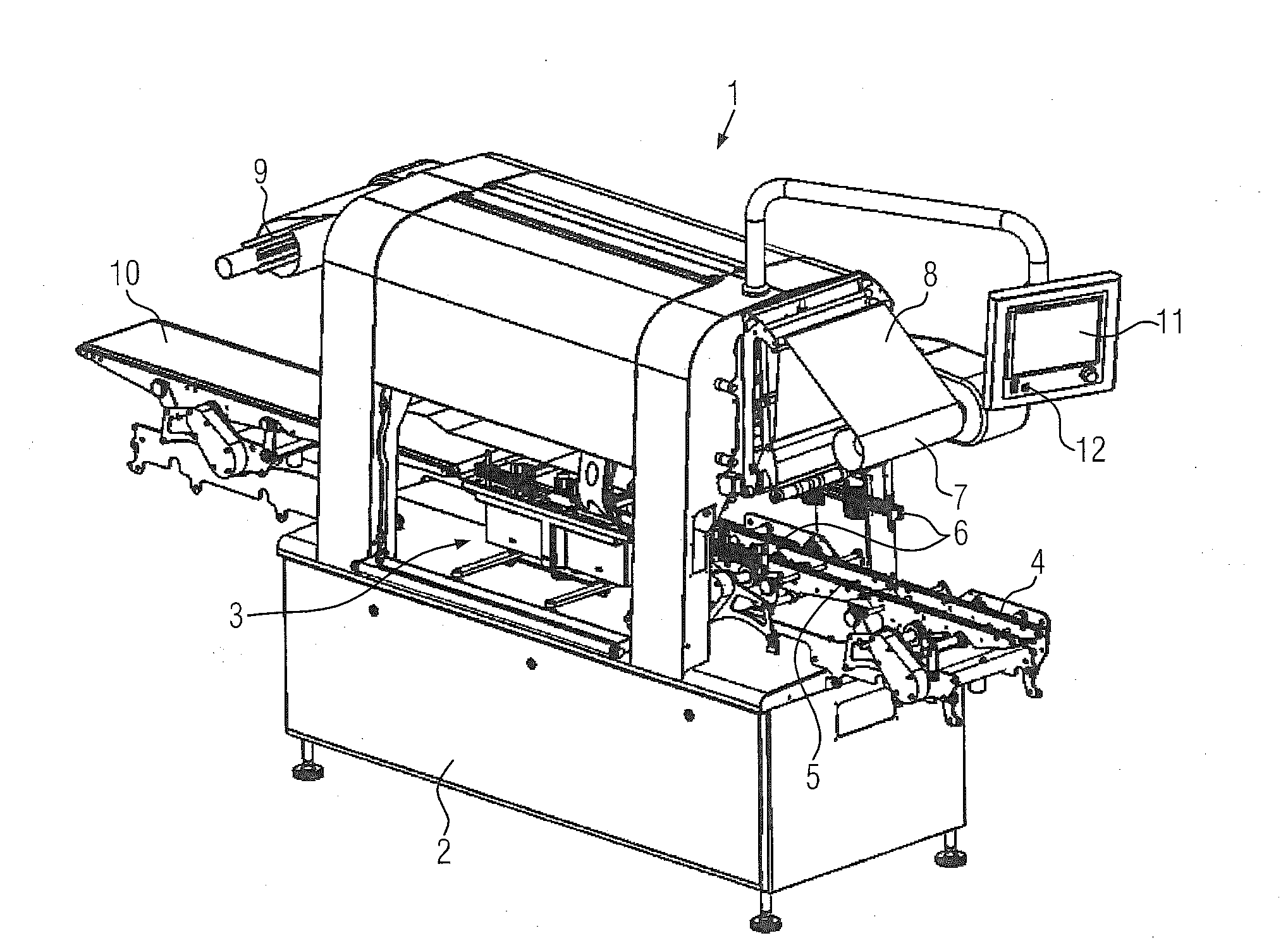
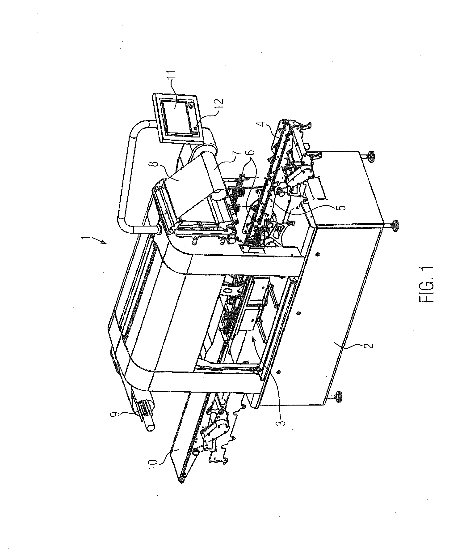
[0025]FIG. 1 shows in a perspective view a tray sealer 1 ac...


PUM


Abstract

The invention relates to a tray sealer comprising conveyor belts that can be displaced in a direction transversely to the conveying direction.

Description

CROSS-REFERENCE TO RELATED APPLICATION[0001]This Application claims priority to German Application Number 102011106826.4 filed Jul. 7, 2011 to Wolfgang Negele entitled “Tray Sealer,” currently pending, the entire disclosure of which is incorporated herein by reference.FIELD OF INVENTION[0002]The invention relates generally to a tray sealer.BACKGROUND[0003]Tray sealers of the type offered also by the applicant are disclosed in DE 10 2008 030 510 A1. In order to achieve high performance, belt speeds and belt accelerations can be varied by the operator making use of the machine control. In regards to high belt speeds and belt accelerations, it is of decisive importance that the bottom of the tray filled with a product adheres to the belt surface of the conveyor. The adherence may also change during the production process due to an increase in air humidity or due to liquid product residues, and this leads to malpositioning on the collecting belt. A gripper system may then perhaps no lon...

Claims


Application Information

Patent Timeline
Patent Type & Authority Applications(United States)
IPC IPC(8): B65B7/28
CPCB65B7/164B65G15/12B65B43/52B65B35/24
Inventor NEGELE, WOLFGANG
Owner MULTIVAC SEPP HAGGENMULLER GMBH & CO KG
Why Eureka
Try Eureka